- A powerful 90V DC motor with electronic speed controller*
- 2.75" (70mm) x 6.0" (152mm) crosslide
- 15" (381mm) steel bed to allow 8" (203mm) between centers
- Standard 1-5/8" (41mm) laser-engraved aluminum handwheels
- Pulleys, drive belt, faceplate, lathe dog, two dead centers, three hexagonal keys, tool post, sharpened high-speed steel cutting tool, eight-foot three-wire power cord, and instruction manual
-
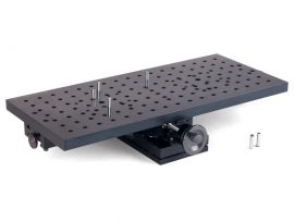
From the Bottom: Four 1/4-20 holes on 2" centers in the base for mounting from below.
-
From the Top: If bottom access is unavailable, use the included four angle clamps that fit into the perimeter groove of the base. Drill and tap the mounting surface for the included 10-32 socket head cap screws. Use all four clamps for maximum stability.
-
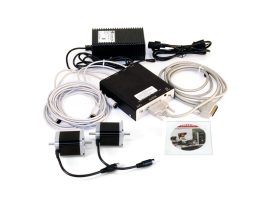
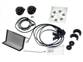
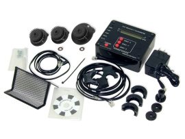
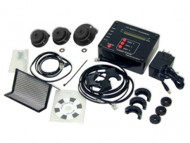
Single-axis slide with your choice of 8", 13", or 18" table
-
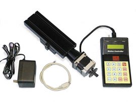
Linear controller with integrated keypad
-
Power supply
-
NEMA #23 frame size stepper motor
-
1-5/8" handwheel, graduated in .001" increments (inch) or .01 mm increments (metric)
-
Cables
-
Complete instructions
- Inch models show position to 0.0005″ (three and a half decimal places)
- Metric models show position to 0.01 mm
- 15″ (381 mm) steel bed giving 8″ (203 mm) between centers
- Maximum diameter over bed: 3.50″ (90 mm)
- Crosslide travel: 2.75″ × 6.00″ (70 mm × 152 mm)
- 90 V DC motor with electronic speed control – continuously variable 70–2,800 RPM (no belt changes required)*
- DRO handwheels on leadscrew and crosslide
- DRO (Digital Readout) – precise, repeatable positioning, improving accuracy over handwheel-only control
- DRO readout box, DRO-compatible handwheels / encoder setup
- Pulleys, drive belt, faceplate, lathe dog
- Two dead centers
- Three hex keys
- Standard tool post
- Sharpened high-speed steel cutting tool
- Grounded 3-wire power cord (8 ft)
- Instruction manual
- CNC-ready with factory-installed stepper motor mounts (X and Z axes)
- Turns parts up to 3.5″ (90 mm) diameter over the bed
- 15″ (381 mm) bed provides extended travel for longer workpieces
- 6″ (152 mm) crosslide for increased tool reach
- Precision-machined dovetail slides with adjustable gibs and backlash
- High-accuracy spindle and headstock used across all Sherline lathes
- Manual control possible with included handwheels
- Compatible with Sherline’s full line of accessories
- Made in the USA
- Model making and miniatures
- Prototyping and custom part production
- Educational CNC training programs
- Hobbyist and light industrial use
- Adjustable resettable “zero” handwheels: 2.5″ (63 mm) on the leadscrew, 2″ (51 mm) on both the crosslide feed screw and the tailstock - each handwheel has laser-engraved aluminum handwheel collars
- Turns parts up to 3.5″ (90 mm) diameter over the bed and 1.75" (45 mm) over the carriage without riser blocks; with riser blocks, up to 6″ over the bed
- 17″ (430 mm) bed provides extended travel for longer workpieces
- 6″ (152 mm) crosslide for increased tool reach
- Precision-machined dovetail slides with adjustable gibs and backlash
- High-accuracy spindle and headstock used across all Sherline lathes
- Spindle speed: continuously variable from 70 to 2,800 RPM via electronic control (no belt changes required). A second pulley position offers more torque at low RPM if needed
- Rocker-style tool post (replacing the standard post used on shorter lathes)*
- Comes with pulleys, drive belt, faceplate, lathe dog, two dead centers, three hex keys, rocker tool post, a sharpened high-speed steel cutting tool, a grounded 3-wire power cord (8 ft), and instruction manual
- Compatible with Sherline’s full line of accessories
- Made in the USA
- Inch models show position to 0.0005″ (three and a half decimal places)
- Metric models show position to 0.01 mm
- 24″ (610 mm) steel bed giving 17″ (431 mm) between centers
- Maximum diameter over bed: 3.50″ (90 mm)
- Crosslide travel: 2.75″ × 6.00″ (70 mm × 152 mm)
- 90 V DC motor with electronic speed control - continuously variable 70–2,800 RPM (no belt changes required)*
- DRO handwheels on leadscrew and crosslide
- Rocker-style tool post included
- DRO (Digital Readout) - precise, repeatable positioning, improving accuracy over handwheel-only control
- DRO readout box, DRO-compatible handwheels / encoder setup
- Pulleys, drive belt, faceplate, lathe dog
- Two dead centers
- Three hex keys
- Rocker tool post
- Sharpened high-speed steel cutting tool
- Grounded 3-wire power cord (8 ft)
- Instruction manual
- CNC-ready with factory-installed stepper motor mounts (X and Z axes)
- Turns parts up to 3.5″ (90 mm) diameter over the bed
- 17″ (430 mm) bed provides extended travel for longer workpieces
- 8″ (200 mm) crosslide for increased tool reach
- Precision-machined dovetail slides with adjustable gibs and backlash
- High-accuracy spindle and headstock used across all Sherline lathes
- Manual control possible with included handwheels
- Compatible with Sherline’s full line of accessories
- Made in the USA
- Model making and miniatures
- Prototyping and custom part production
- Educational CNC training programs
- Hobbyist and light industrial use
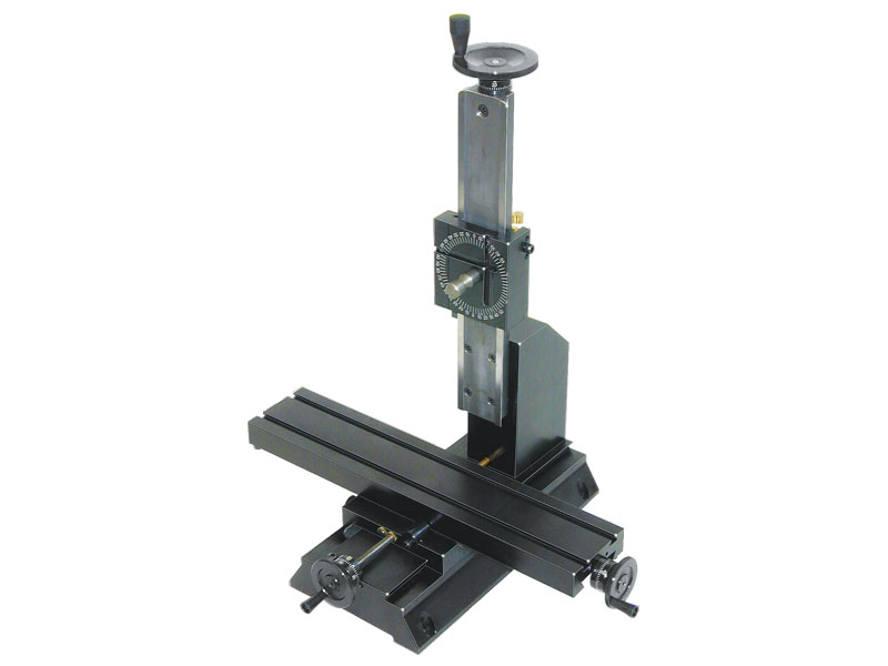
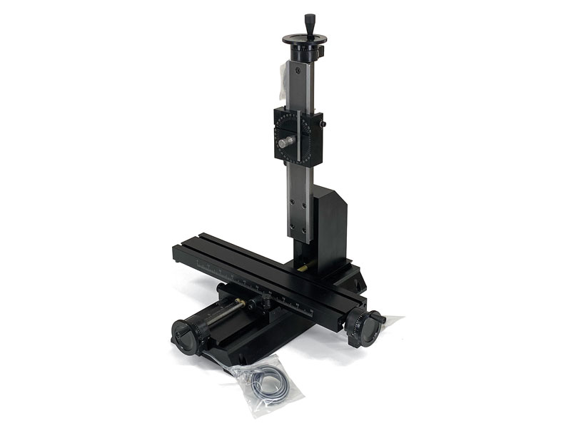
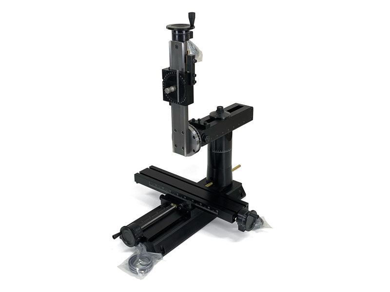
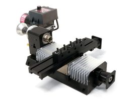
10″ Tabletop Mill XYZ Base – CNC Ready
NOTE: CNC-ready machines cannot be operated manually until stepper motors are installed.
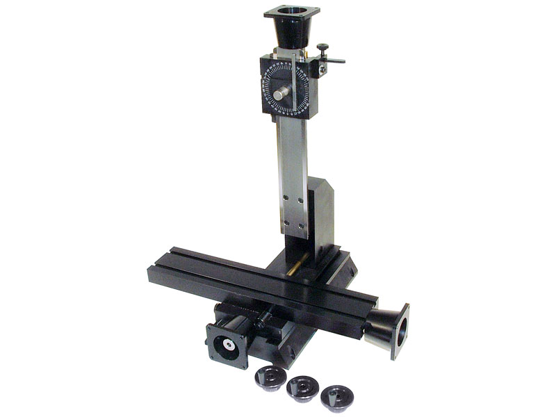
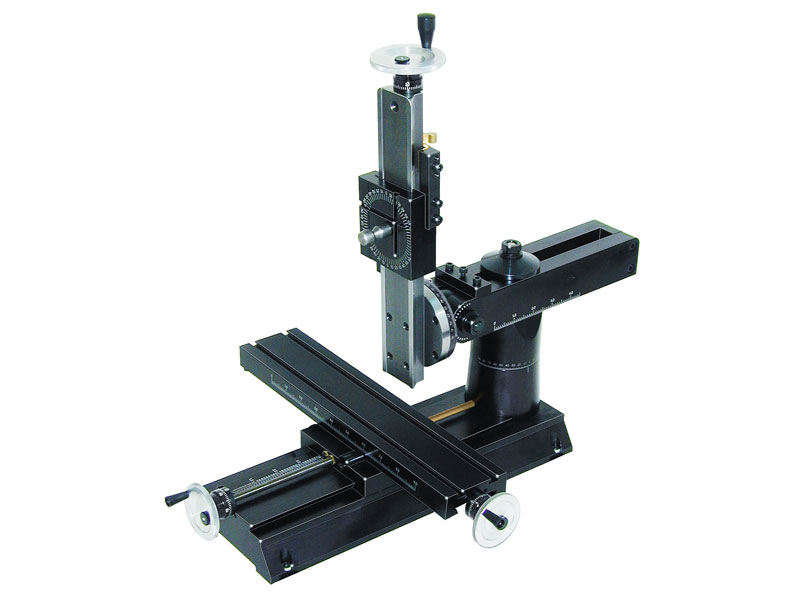
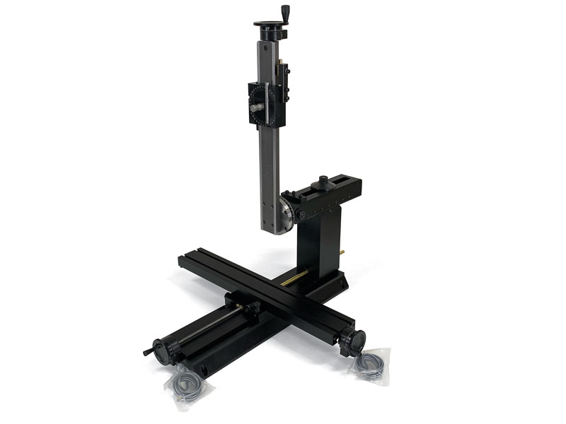
12″ Deluxe Tabletop Mill XYZ Base – CNC Ready
NOTE: CNC-ready machines cannot be operated manually unless double-shaft stepper motors are installed.
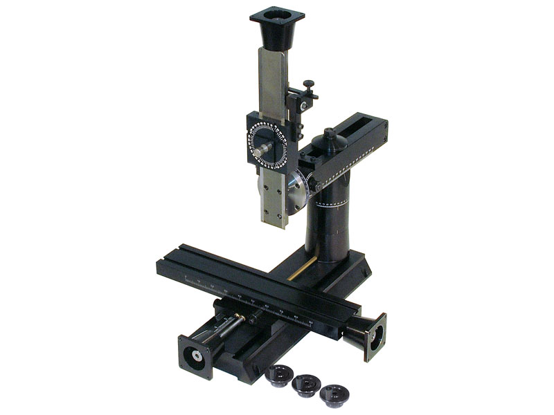
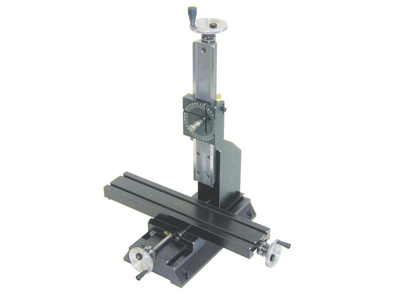
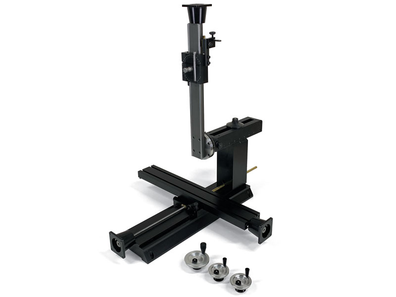
14″ 8-Direction Benchtop Mill XYZ Base – CNC Ready
NOTE: CNC-ready machines cannot be operated manually unless double-shaft stepper motors are installed.
14″ 8-Direction Benchtop Mill XYZ Base – DRO
Purpose of the Sherline Benchtop Mill XYZ Bases The Sherline vertical mill can be purchased without the headstock and motor/speed control. This allows lathe owners to swap the headstock and motor/speed control from their lathe to the mill in approximately … Continued
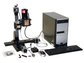
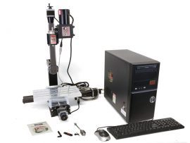
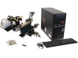
12″ Deluxe CNC Tabletop Mill System
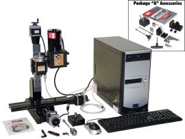
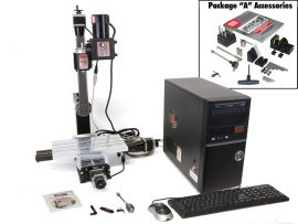
12″ Deluxe CNC Tabletop Mill System Package A
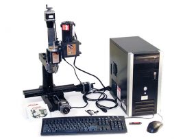
14″ 8-direction CNC Benchtop Mill System
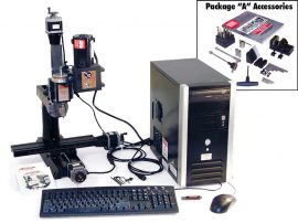
14″ 8-direction CNC Benchtop Mill Package A
18″ NexGen CNC Benchtop Mill System
18″ NexGen CNC Benchtop Mill System Package A
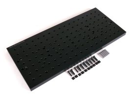
8″ x 18″ Laser Engraving Plate
Chucker Lathe
NexGen Mill Column – Manual
NexGen Mill Column – DRO
2-Axis Lathe DRO
2-Axis Lathe DRO without Readout Box
3-Axis Lathe DRO
Mill Digital Readout (DRO)
Mill DRO with CNC Thrust Collars

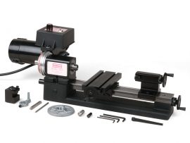
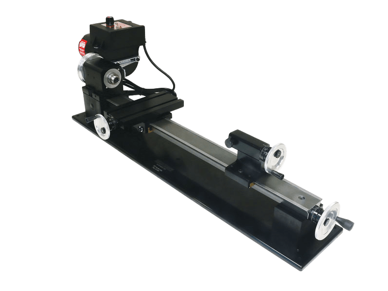
8″ Tabletop Lathe
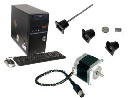
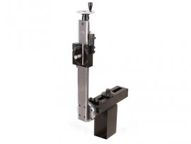
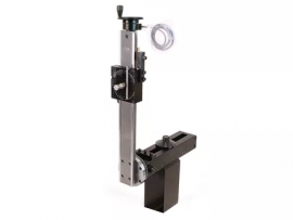
Single-Axis Slide with Programmable CNC Contoller
Sherline’s single-axis controllers are designed to drive the stepper motor on any individual axis of a lathe or mill—no separate computer or driver is required. Each controller features an integrated computer chip within the keypad/control unit, allowing you to operate the motor directly from the keypad or enter simple programmed sequences—no G-code knowledge needed.
You can program parameters such as direction, travel distance, feed rate, and whether to pause between operations or proceed automatically to the next step. The controller can store up to 40 steps (each with four parameters) in either of two user-defined programs. Multiple controllers can be linked via cable to synchronize movements or can be connected to a larger CNC system using “sense” and “acknowledge” signals to coordinate actions within a CNC sequence.
Stepper Motor Mounting & Drive System
Each stepper motor mount includes dual ball bearings with a preload nut to eliminate endplay. A dampened coupling connects the motor’s 1/4" diameter shaft to the leadscrew. The dual-shaft stepper motor also allows for manual operation using the provided handwheel. The controller employs micro-stepping for precise, smooth movement.
Mounting Options
Included Components (Linear Machine Slide with Programmable Controller)
Power Supply
The included power supply operates on 115/120 VAC, 60 Hz (38 W). For regions with 100, 220, or 240 VAC and/or 50 Hz power, a step-down transformer is required. Alternatively, you may supply 24VDC, 1A (1000 mA) from a compatible local power source. Sherline does not offer a 220V power supply or transformer.
Weight Capacity
The slide has a weight capacity of approximately 10 lbs, depending on table length and load placement. For an 18" table, limit off-center loads (at the table end) to no more than 10 lbs. Heavier loads may be supported if centered near the base.
Duty Cycle & Maintenance
Under heavy, continuous use, you may observe wear on the anodized dovetail surfaces after one year (approx. 2080 hours). The slide remains fully functional, but regular lubrication with light oil is recommended to maximize lifespan.
IMPORTANT: Do not use WD-40 for lubrication. It will strip the anodized coating.
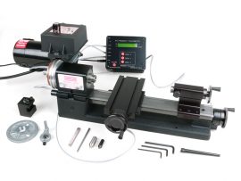
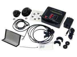
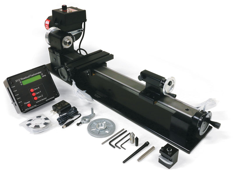
8″ Tabletop Lathe with DRO
Our 8″ DRO Benchtop lathes includes a digital readout box and specialized handwheels with built-in electronic encoders that replace the standard handwheels (standard handwheels are not included with the DRO option). These DRO handwheels interface with the readout box, which translates handwheel movement into precise digital readings for each axis. Each axis can be zeroed at any time with the push of a button, and the DRO continuously displays spindle RPM whenever the motor is running. The readout is compatible with both inch and metric machines.
This compact DRO lathe is ideal for customers who need a small-format machine capable of producing highly accurate, precision parts. Proudly made in the USA, all our lathes are backed by exceptional customer support. Despite its desktop size, this machine delivers full-size performance – capable of cutting wood, plastic, aluminum, and even steel with excellent rigidity and accuracy.
Using the DRO System
The DRO displays each axis position relative to a zero point you set.
The system supports both ball screw and leadscrew machines. As well as the ability to use Metric DROs on inch machines or inch DROs on metric machines. It features six selectable modes based on machine type (mill or lathe), screw type (leadscrew or ball screw), and preferred display units (inch or metric). For setup instructions, refer to the official DRO Mode Instructions.
You can electronically compensate for backlash by inputting the measured backlash value for each axis. When the direction of handwheel rotation reverses, the DRO subtracts the backlash before updating the position – eliminating common errors and making it easier to track travel distance and direction. The power supply automatically switches between 120V and 240V, making it suitable for use in countries with 220–240V electrical current. A socket adapter may be required outside North America.
Features of the 8″ Benchtop Lathe
What’s Included
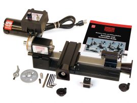
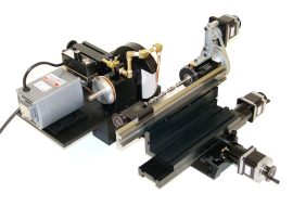
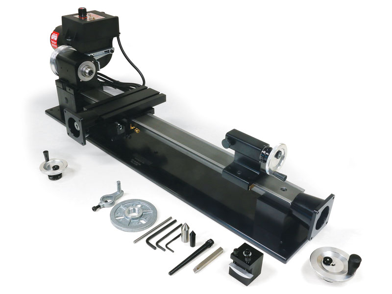
8″ Tabletop Lathe – CNC Ready
The Sherline 8″ CNC Lathe is a precision benchtop machine designed for small, detailed, and accurate turning applications. Built on Sherline’s proven lathe platform, this CNC-ready version includes factory-installed stepper motor mounts on both the X and Z axes – allowing you to add your own stepper motors and controller for complete CNC control.
With a 15″ long bed, 6″ crosslide, and a working diameter capacity of up to 3.5″ over the bed, this lathe provides the versatility needed for prototyping, small-part production, model engineering, R&D, and teaching environments. The rigid aluminum/steel construction, dovetail slides, and adjustable backlash compensation ensure repeatable accuracy on even the smallest parts.
All CNC-ready Sherline lathes include the same high-quality headstock, spindle, and bearings used in our manual models, giving you excellent spindle concentricity for demanding turning operations. The machine still allows for full manual operation when needed – simply turn the handwheels for quick setup or manual machining tasks.
Features:
Ideal Applications:
Note: This is a CNC-ready lathe. Stepper motors and CNC controller are sold separately. For a fully assembled and tested system, see our complete CNC lathes.
17″ Benchtop Lathe
Our benchtop lathe offers 17″ between centers, more than double the 8″ available on the tabletop model, giving you significantly more clearance. This extra space becomes especially useful when a part is held in a chuck and the tailstock also holds a larger drill chuck with a long bit, where a shorter bed might fall short.
With the additional 9″ of center-to-center distance, along with adjustable “zero” handwheels and a rocker-style tool post, this lathe brings more flexibility and capability - a worthwhile upgrade over the shorter version.
Although compact in size, our 17″ benchtop lathe still delivers the precision and accuracy expected from a full-size machine. It’s capable of turning wood and plastic, but is also rigid enough to handle aluminum and steel parts - making it suitable not just for hobby use, but for precision metalwork too.
Designed as a desktop-friendly machine, it packs full-size performance into a smaller footprint, offering a practical balance of convenience and capability for small shops or home workshops.
Features:
17″ Benchtop Lathe with DRO
Our 17″ DRO Benchtop lathes includes a digital readout box and specialized handwheels with built-in electronic encoders that replace the standard handwheels (standard handwheels are not included with the DRO option). These DRO handwheels interface with the readout box, which translates handwheel movement into precise digital readings for each axis. Each axis can be zeroed at any time with the push of a button, and the DRO continuously displays spindle RPM whenever the motor is running. The readout is compatible with both inch and metric machines.
This compact DRO lathe is ideal for customers who need a small-format machine capable of producing highly accurate, precision parts. Proudly made in the USA, all our lathes are backed by exceptional customer support. Despite its desktop size, this machine delivers full-size performance - capable of cutting wood, plastic, aluminum, and even steel with excellent rigidity and accuracy.
Using the DRO System
The DRO displays each axis position relative to a zero point you set.
The system supports both ball screw and leadscrew machines. As well as the ability to use Metric DROs on inch machines or inch DROs on metric machines. It features six selectable modes based on machine type (mill or lathe), screw type (leadscrew or ball screw), and preferred display units (inch or metric). For setup instructions, refer to the official DRO Mode Instructions.
You can electronically compensate for backlash by inputting the measured backlash value for each axis. When the direction of handwheel rotation reverses, the DRO subtracts the backlash before updating the position - eliminating common errors and making it easier to track travel distance and direction. The power supply automatically switches between 120V and 240V, making it suitable for use in countries with 220–240V electrical current. A socket adapter may be required outside North America.
Features of the 17" Benchtop Lathe
What's Included
17″ CNC-Ready Lathe
The Sherline 17" CNC Lathe is a precision benchtop machine designed for small, detailed, and accurate turning applications. Built on Sherline’s proven lathe platform, this CNC-ready version includes factory-installed stepper motor mounts on both the X and Z axes - allowing you to add your own stepper motors and controller for complete CNC control.
With a 17" long bed, 8" crosslide, and a working diameter capacity of up to 3.5" over the bed, this lathe provides the versatility needed for prototyping, small-part production, model engineering, R&D, and teaching environments. The rigid aluminum/steel construction, dovetail slides, and adjustable backlash compensation ensure repeatable accuracy on even the smallest parts.
All CNC-ready Sherline lathes include the same high-quality headstock, spindle, and bearings used in our manual models, giving you excellent spindle concentricity for demanding turning operations. The machine still allows for full manual operation when needed - simply turn the handwheels for quick setup or manual machining tasks.
Features:
Ideal Applications:
Note: This is a CNC-ready lathe. Stepper motors and CNC controller are sold separately. For a fully assembled and tested system, see our complete CNC lathes.