If you are making special tooling or a custom accessory for your Sherline tools, this will save you the trouble of measuring your particular machine to find a dimension, some of which are actually quite difficult to measure. If you need a dimension not listed here, please call or write with your request.
Most of the regular specifications can be found by looking at the Lathe and Mill product pages which have a Specifications List tab.
| LOCATION | DIMENSION |
| Bed dovetail angle | 55.5 degrees* |
| Lathe bed to spindle centerline | 1.75″ |
| Lathe table surface to spindle centerline (calculated) | .940″ |
| Headstock spindle nose internal taper | #1 Morse |
| Lathe tailstock internal taper | #0 Morse |
| Headstock spindle external thread | 3/4-16 |
| Pulley groove side angle | 19° |
| Table T-slot centerline distance (lathe and mill) | 1.5″ |
| T-slot nominal dimensions**
**Note: The T-slots are extruded into the material. Table surfaces are machined for flatness, but the slots themselves require no additional finishing processes. |
Slot width, top: .25″ T width, bottom: .40″ Upper slot depth: .10″ T Slot depth: .10″ (Total depth: .20″) |
| Leadscrew thread pitch, inch (Lathe Y axis, Mill X and Y axis = 1/4-20, Lathe and Mill Z axis = 3/8-20) | 20 threads per inch or .050″ travel per revolution (handwheels divided into 50 increments of .001″) |
| Leadscrew thread pitch, metric (Lathe Y axis, Mill X and Y axis = 6.3 x 1 mm, Lathe and Mill Z = 10 x 1 mm) | 1 mm travel per revolution (handwheels divided into 100 increments of .01mm) |
| Leadscrew thread directions | Right-hand: Lathe crosslide, Mill X-axisLeft-hand: Lathe leadscrew and tailstock screw, Mill Y-axis and Z-axis |
| *NOTE: This dimension was determined by measuring the extruded bases that were supplied when we first took over production in the USA from the former Australian manufacturer. The base and several other parts were cast to match this angle and it was not economically feasible at the time to change it to an easier-to-manufacture 60 degrees. The original 55-degree angle was determined by a reference to Machinery’s Handbook, Vol. 17 as the ideal angle to cut a dovetail. When we took over production, a fixture was produced in-house to duplicate the existing angle which had changed slightly from the original 55° to an actual 55.5°. This fixture became the “standard”, and every machine built since the early 1970’s has been measured against this same fixture. The older brass beds and the current steel beds, as well as the parts that fit them, are all ground to this same angle. | |
| ALLOWABLE TOLERANCES | |
| Spindle Runout (at spindle nose), Maximum allowable (Most are within .0002-.0003″) | 0.0005″ |
| Spindle End Play (adjustable with preload nut), Factory Settings | with 2800 RPM Pulleys: 0.0002″with 10,000 RPM Pulleys: 0.0003″ |
| Self-Centering 3-jaw and 4-jaw chuck runout | 0.003″ or less |
| Leadscrew thread pitch accuracy | ±0.001″ per inch of travel |
| COLLETS | |
| Sherline WW Collet body diameter | 0.312″ to 0.313″ |
| 8 mm WW collets (by others), body diameter | 0.314″ to 0.315″ |
| WW and 8 mm collet thread | .275-40 |
| HEADSTOCK BEARINGS | |
| Designation/stock number (ZZ refers to “double shielded”) | 6004ZZ |
| Size of bore | 20 mm (0.7874″) |
| Tolerance of bore | 0.0004″ |
| Outside Diameter | 42 mm (1.6535″) |
| Tolerance of OD | 0.0005″ |
| Width | 12 mm (0.4724″) |
| Bearings | 9 balls, 1/4″ Dia. |
Historical Note
You might find it interesting to note that a problem similar to the one mentioned above is probably why Morse tapers are not perfectly consistent to this day. A Morse taper is listed as “about 5/8″ per foot”. Standard fixtures were probably made years ago and machines and tools over the years were made to match these fixtures. Modern measurement techniques were able to establish that these fixtures were not all perfectly consistent in angle. Changing the angle, however, would make it impossible for new parts to fit the old machines. Therefore, today we have Morse tapers that each varies slightly from a taper of 5/8″ (.6250″) per foot. The actual tapers for each number Morse taper are as follows:
| MORSE TAPER # | TAPER PER FT. | TAPER PER IN. |
| 0 | .62460 | .05205 |
| 1 | .59858 | .04988 |
| 2 | .59941 | .04995 |
| 3 | .60235 | .05019 |
| 4 | .62326 | .05193 |
| 5 | .63151 | .05262 |
| 6 | .62565 | .05213 |
| 7 | .62400 | .05200 |
More on dimensions…what is a Micron?
While we are talking dimensions and tolerances, you may find that some people, most often in the scientific community, speak in microns. A micron is defined as a millionth of a meter or a thousandth of a millimeter (.001 mm). The inch equivalent of this would be .00003937″ which is usually rounded off to .00004″ or a little less than a half of one ten-thousandth of an inch. This means there are about 25 microns in .001″, or 100 microns would be about .004″ (or more exactly 0.003937″).
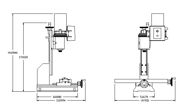
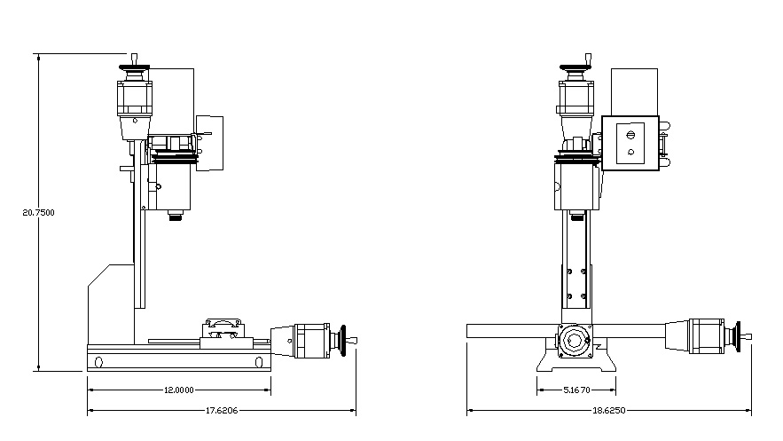
Sherline Tool Dimensions
John Costello has done some AutoCad drawings that show the basic overall dimensions of our lathes and mills. Click on any drawing and use the “forward” and “previous” arrows to scroll through the images of the Sherline machines. To end the tour just click in the gray area.
-
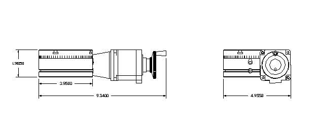
- 4000/4100 Lathe
-
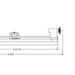
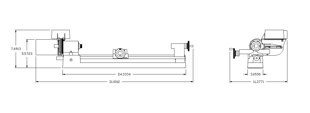
- 4400/4410 Lathe
-
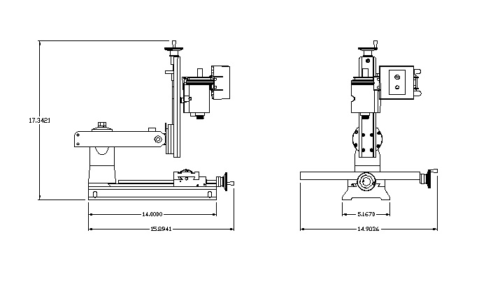
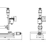
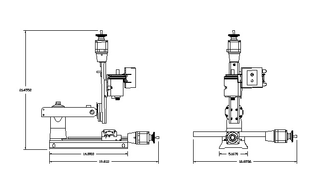
- 5000/5100 Mill
-
- 5400/5410 MIll
-
- 2000/2010 Mill
-
- 8400/8410 CNC Lathe
-
- 8440/8441 CNC Lathe
-
- 8020/8021 CNC Mill
-

- 8540/8541 CNC Mill

-

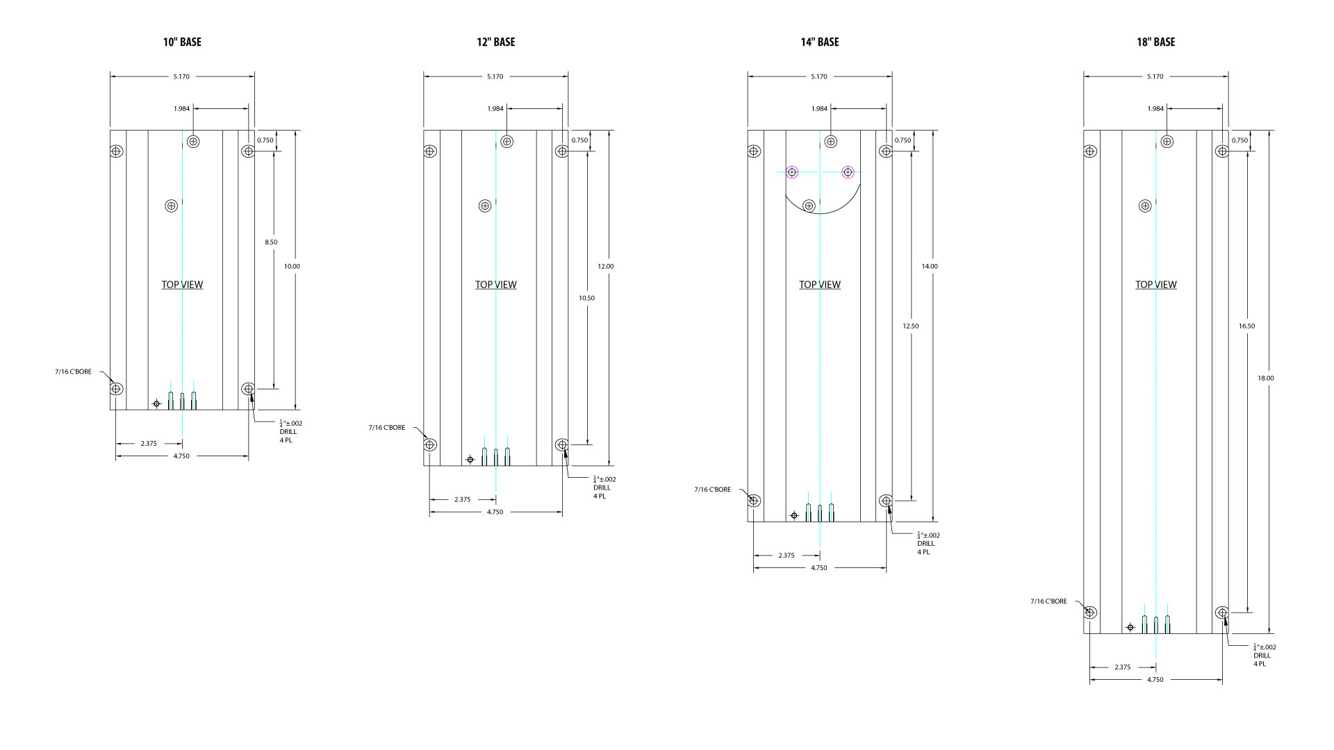
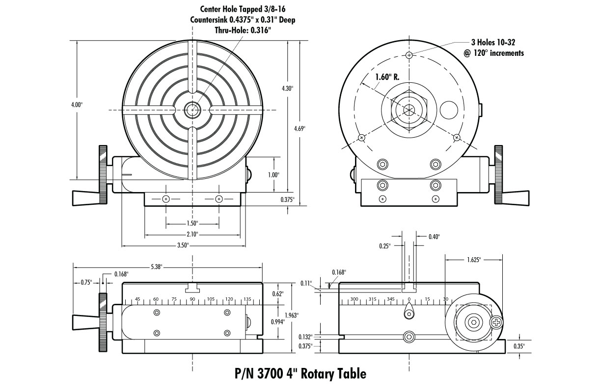
- 3700 Manual Rotary Table
-

- 8730 CNC Rotary Table
-
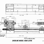
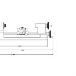
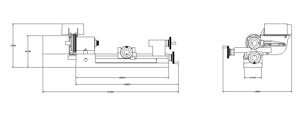
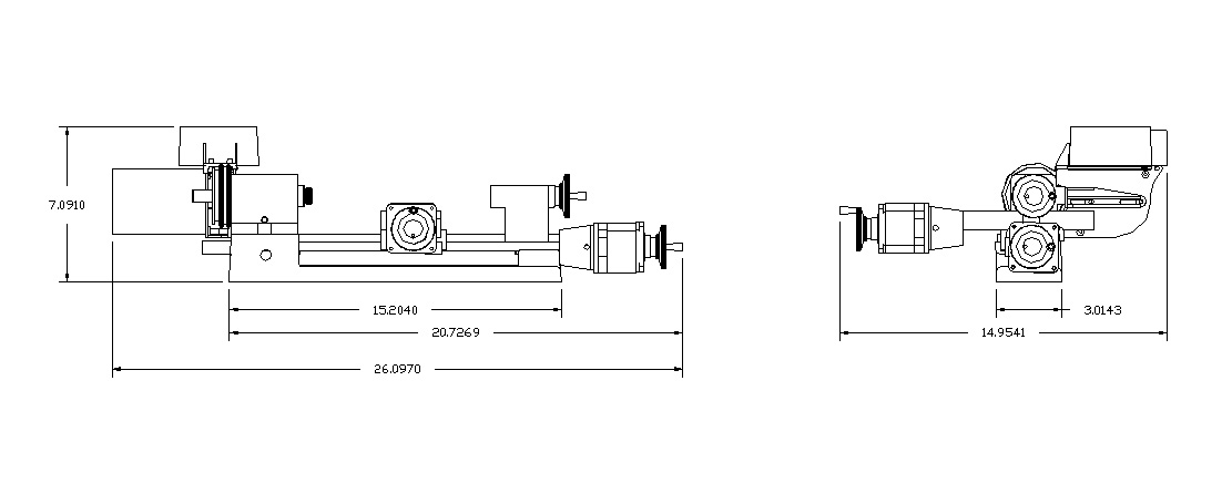
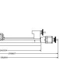
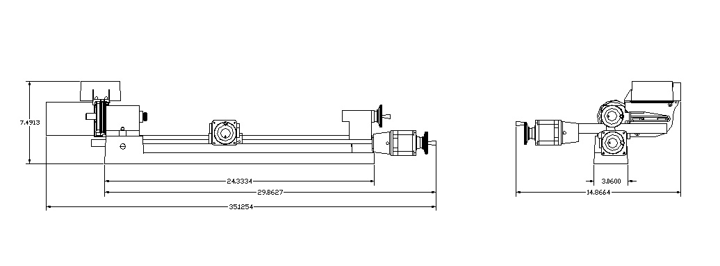
- 4000 Lathe Cross-section
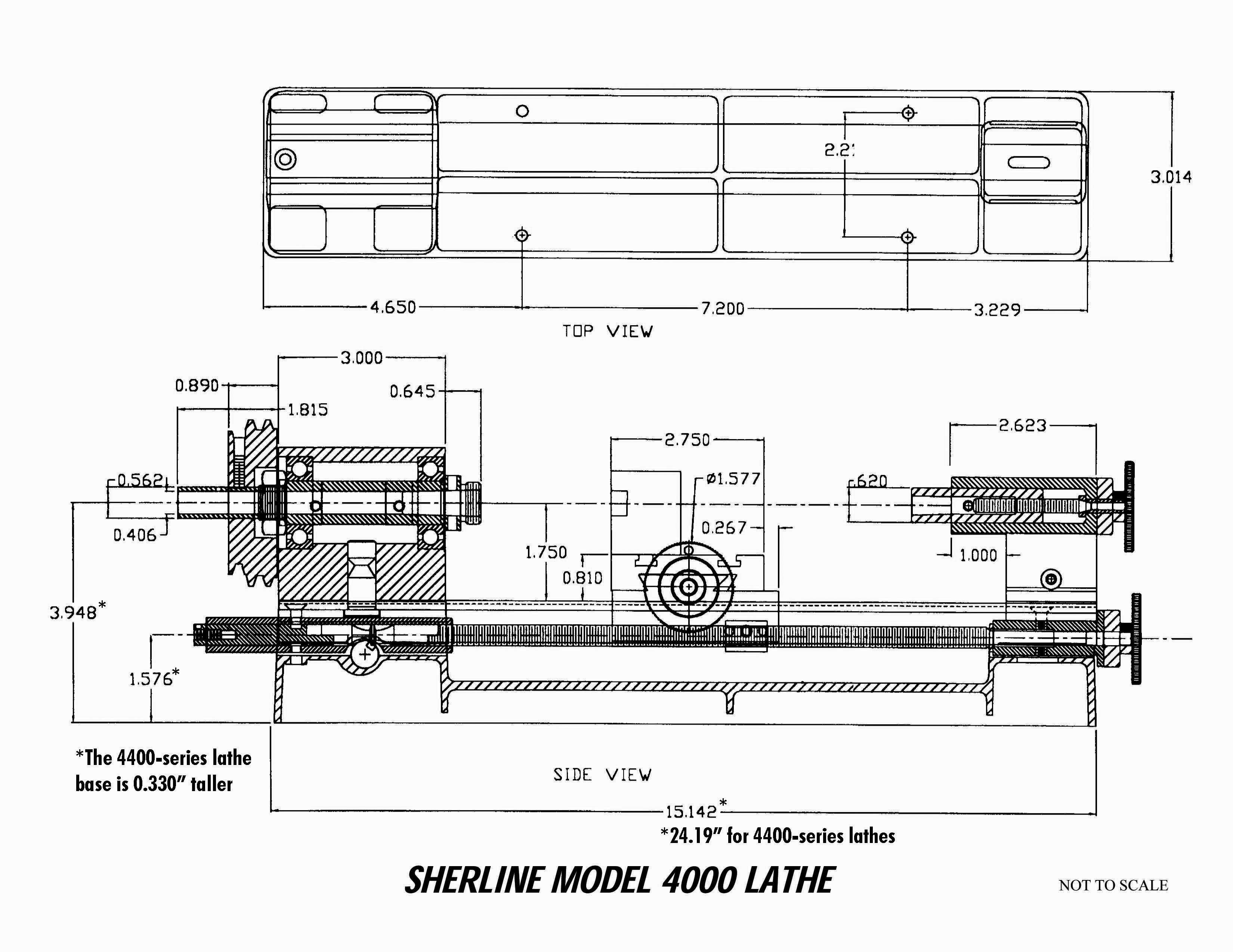
The drawing of the Lathe Cross-section above shows the key dimensions on a Sherline Model 4000 lathe. It is provided to help those who wish to make special equipment to fit your lathe. Note that the longer 4400-series version of the lathe has a taller cast base for more rigidity. It is 0.33″ taller overall and 9″ longer.
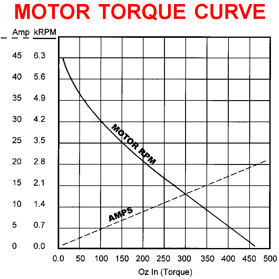
Electric Motor Specifications from Manufacturer
- Type of enclosure: Totally enclosed, non-vented
- Duty rating: Continuous–10 oz. in. at 6100 rpm, .85 amperes; Intermittent–30 oz. in. at 5500 rpm, 1.75 amperes (5 minutes on / 15 minutes off)
- Output horsepower: .06 KW (60 W) at 10 oz. in. / 6100 rpm
- AC voltage (input): Normally 115 VAC, 60 Hz, Single Phase to a rectifier (Sherline electronic speed control converts any input from 100 VAC to 240 VAC, 50-60 Hz.)
- DC voltage: 90V DC to motor (60 Hz)
- Speed in rpm: 6100 rpm continuous
- Class of insulation: Class A, 105° (C.) insulation system
- Normal full load current: .85 amperes
- Starting current: 1.7 amperes instantaneous starting current (<100 milliamperes). This is also the stall current in True RMS
- Max current at time of changeover from lower speed to higher speed: Depends on load
- Type of motor: 3.00 inch (outer diameter) sub-fractional horsepower brush-type permanent magnet motor
- Temperature rise at ambient 50° C.: Less than or equal to 45° C.
- Motor frame size: 3 inches
- End use of motor: Drive unit for lathe or mill
NOTE: Electronic circuitry built into the speed control supplies a constant 90 VDC output to the motor regardless of the input current from 100VAC to 240VAC, 50 or 60 Hz, so Sherline machines can be plugged in and used in any country in the world without a transformer as long as you have the correct wall plug converter..
USE WITH AN INVERTER: This motor and speed control can be used with an inverter that produces a sine wave. It cannot be used with an inverter that produces a square wave.