Standard Machining FAQs
Machine Capabilities & Specifications
There are virtually no limits to the materials you can machine—from wood and plastic to more challenging materials like stainless steel and Inconel. As long as the part is securely held and the appropriate cutting tool and speed are used, a wide range of materials can be successfully machined. To watch short video clips of materials being cut, from Delrin to Inconel, click here.
The Sherline lathe can turn parts up to 3.5″ (90 mm) in diameter over the bed. However, this does not mean you can turn a full 3.5″ diameter part between centers, as the crosslide limits clearance. Over the crosslide, the maximum turning diameter is 1.875″ (48 mm). Installing a 1.25″ riser block kit increases the capacity to over 5.5″ (140 mm) over the bed and 4.3″ (109 mm) over the crosslide. The headstock features a .405″ (10 mm) through-hole, allowing bar stock of that diameter to pass through for machining. The standard lathe offers 8″ between centers, while the long bed version provides 17″.
These figures represent the machine’s physical limits, but material hardness also plays a significant role in practical performance. As a general rule, take the average diameter of the parts you intend to machine and multiply it by three for free-machining materials (like aluminum, brass, or free-machining steel) or by four for tougher materials (like stainless steel). For example, a Sherline lathe will perform well on free-machining materials with average part diameters of about 1″ (25 mm).
Wood and plastic are easy to cut, so size is the primary consideration. While it’s possible to turn a 3″ flywheel on this lathe, frequent machining of large parts may be better suited to a larger machine with more horsepower. Removing substantial material on a small lathe takes time, so if time is not a constraint, part size becomes less of a factor. Overall, users are more satisfied when working well within a machine’s capabilities. If most of your parts are small and only occasionally push the machine’s limits, you’ll likely be very pleased with the lathe’s performance.
The Sherline vertical milling machine can handle larger parts than the lathe because the part remains stationary while the cutting tool rotates. It also features a longer X-axis travel. The deluxe mill adds 2″ of Y-axis travel compared to the standard model and includes a headstock spacer block that increases the throat distance (tool-to-column clearance) by 1.25″.
With the optional horizontal milling conversion, surfaces up to 6″ x 9″ can be machined in a single setup without repositioning the part—an impressive capacity for such a compact machine.
The 90-volt DC motor provides significantly more torque than the older 1/2 HP AC/DC motors previously used. It also runs much smoother and quieter. The electronic speed control is designed to automatically adapt to input voltages worldwide, from 100 to 240 volts, 50 or 60 Hz. (For complete motor specifications and torque curve charts, refer to the Sherline tool dimensions file.)
An integrated electronic circuit maintains consistent RPM under varying loads, compensating automatically during cutting operations. Users are often surprised by the motor’s impressive power and smooth operation.
The electronically controlled speed range spans from 70 to 2800 RPM, requiring no gear or belt changes. Simply turn the speed control knob to select any speed within that range—for instance, halfway is approximately 1400 RPM. Precise RPM measurement isn’t required; with experience, you’ll learn to adjust speed by observing chip formation and listening to the cut.
For additional torque at lower speeds—such as when turning larger parts—a second belt position is available on the motor and headstock pulleys.
(As a side note, purchasing a DC motor and speed control of this quality separately could cost more than the entire Model 4000 lathe.)
We also make a high-speed pulley set that allows the motor to drive the spindle at speeds up to 10,000 RPM. This kit can be retrofitted to any existing Sherline machine equipped with the DC motor. Alternatively, a complete headstock assembly with the high-speed pulley set pre-installed is available. The pulley system also includes a second position for a lower-speed, high-torque range, with a maximum of 2200 RPM. Higher spindle speeds are especially useful when turning small-diameter parts or using fine cutting tools.
Traditional machining operations typically involve short duty cycles, where the machinist performs a task, then pauses the machine to measure or change parts. However, with the introduction of software-generated 3D CNC programs—often thousands of lines long—Sherline machines are now frequently run for extended periods, sometimes several hours at a time.
The DC motor used in Sherline machines was specifically selected because it meets essential criteria for size, cost, RPM range, torque (especially at low speeds), noise level, and weight. In contrast, AC motors of similar performance are significantly larger and heavier. Additionally, the Sherline DC motor is fully enclosed, which helps protect internal components from chips and debris that could damage the windings or commutator. The trade-off for this sealed design is reduced cooling efficiency, but we believe the benefits far outweigh the limitations.
Although the motor is rated for continuous use and includes built-in thermal protection that automatically shuts off power if the internal temperature reaches 170°F (77°C), this should not be treated as a safe operating limit. Motor lifespan is directly influenced by how long and how heavily it is used. Running the motor under high loads for 8–12 hours a day will naturally shorten its life more quickly than using it intermittently. High-speed operation also accelerates wear compared to lower RPMs. For this reason, Sherline does not extend the motor warranty for production or industrial use.
Brush Maintenance
The most common wear item in a DC motor is the brushes. To extend motor life, we switched to a motor design that allows brush replacement without disassembling the unit. We recommend checking brush wear approximately every six months. Regular maintenance helps ensure long motor life and consistent performance.
When checking or replacing motor brushes, observe the following precautions:
- Always unplug the machine before servicing.
- Check one brush at a time to avoid mixing them up.
- Reinstall each brush in the same orientation it was removed. Reversing it can cause uneven wear and shorten its lifespan.
- New brushes are 5/8″ (15 mm) long and should be replaced when worn down to 1/4″ (6 mm).
- Never allow the brush to wear down to the spring. This can damage the copper commutator surface, requiring full motor replacement.
By understanding your motor’s limits and performing routine maintenance, you can significantly extend the life of your Sherline spindle motor.
The depth of cut you can take depends primarily on the material type, its diameter, the sharpness of your cutting tool, and the rigidity of your setup. Sherline’s high-torque DC motor delivers impressive power for its size—so much so that users often underestimate its capabilities and feed the cutting tool too slowly, which can result in tool chatter.
For example:
- When cutting aluminum on 3/4″ diameter stock, you can typically take cuts up to .060″ deep.
- For stainless steel, limit your cuts to .015″ or less per pass.
- In free-machining steel, you can take a .015″ cut even on a 3″ diameter part.
Heavy cuts combined with high RPMs can also lead to chatter. To prevent this, ensure you’re feeding the tool aggressively enough to maintain a continuous cut—this keeps the tool engaged with the material.
Rule #1 in machining:
If the tool chatters, reduce RPM, reduce the depth of cut, and increase the feed rate.
To see this principle in action, visit our Video page and watch the “Eliminating Tool Chatter” demonstration video.
With the optional Thread Cutting Attachment, the Sherline lathe can cut nearly any thread size. It supports 31 unified thread pitches ranging from 80 to 10 threads per inch, and 28 metric pitches from 0.25 to 2.0 mm. Both right-hand and left-hand threads can be cut. Additionally, inch threads can be cut on a metric machine and vice versa. This flexibility allows you to cut threads beyond the limitations of standard tap and die sets.
Most milling machines are classified as three-axis machines, meaning they use handwheels to move the part along the X-axis (left/right), Y-axis (in/out), and Z-axis (up/down). In addition to these standard movements, the Sherline mill features a headstock that can be rotated for angled milling. While this allows movement of the cutting tool, it does not constitute an additional axis of part movement.
The Sherline 8-direction mill includes a more advanced ram and column design that allows the headstock to move in and out, pivot side to side, swing back and forth, and rotate horizontally. These four additional directions of headstock movement, combined with the standard three axes, provide a total of eight possible directions for either the part or the cutter to move. However, from a machining standpoint, even the 8-direction mill is still classified as a 3-axis mill, since only three axes involve direct part movement.
A true “4th axis” typically refers to rotary motion, which can be added to any Sherline mill using a rotary table—commonly designated as the “A” axis.
In summary, the Sherline 10″ and 12″ mills are 3-axis mills with one additional headstock adjustment for angled cuts. The 8-direction mill is also a 3-axis mill but offers five extra directions of headstock adjustment for enhanced versatility. While these added features expand setup possibilities, they also require more time to precisely align and square the machine.
The level of mill you need depends on both your experience and the complexity of the work you plan to do. For most beginners, an 8-direction mill is more than necessary. Every time one of the adjustable axes is moved out of square, it must be precisely realigned (“indicated”) before continuing with the next job. This process is standard practice on full-size machines like a Bridgeport®, and every machinist eventually becomes familiar with the task of squaring up their mill.
However, Sherline’s standard mills have fewer adjustable axes, which means fewer opportunities for misalignment and less time spent re-squaring the machine. This is an example of an engineering trade-off—additional capability brings added versatility but also increased setup complexity.
In many cases, setups that require machining from multiple angles can be achieved using accessories like a tilting angle table, which positions the part rather than the headstock. Similarly, angled drilling can be accomplished on a standard mill either with a tilting angle table or by adding a rotary column attachment. These methods are ideal for small parts, though some larger castings may exceed the table’s capacity, making a more versatile mill the better solution.
There is a lot to learn when first operating a milling machine, and starting out with a more complex model can be overwhelming. A new machinist may find it easier and more encouraging to begin with a simpler setup. On the other hand, experienced users will quickly recognize and benefit from the flexibility of a multi-adjustable machine.
If you’re unsure whether you need the full range of movement provided by an 8-direction mill, we recommend starting with a 10″ mill or 12″ mill. You can always upgrade later by adding a column conversion kit, which brings your machine to full 8-direction capability. The cost difference between the 8-direction mill and 12″ mill with the upgrade kit is minimal—so there’s little downside to postponing that decision until you’re certain you need the extra features.
Of course, if cost isn’t a concern and you want the most versatile machine from the start—and are willing to invest the time to learn its full potential—then by all means, go straight for the 8-direction.
The column and ram components on the 8-direction mill provide several additional directions of movement not available on the standard models. During prototype testing, we pushed the machine to its limits by extending the table to the end of its travel and the ram to its maximum overhang, then fly cut a part positioned at the outermost edge of the table. While this is an extreme setup unlikely to be used in typical applications, the machine needed to perform reliably even under such conditions to justify its production.
As with any full-size mill, the further you move from the center of the machine, the more conservative your cuts should be. Nonetheless, the results in this test were quite acceptable. The cross-sectional dimensions of all Sherline mill components are carefully engineered to handle the forces generated by the machine’s motor. Since Sherline mills operate with relatively low horsepower compared to full-size machines, the column and ram provide more than enough rigidity for the expected loads.
Roughing cuts and cutting hard materials should be done with “Conventional Milling.” Finish cuts can be done with “Climb Milling.” Climb milling is, as the name implies, the cutting edge of the tool that is literally climbing up the side of the part. Conventional milling has the cutting edge of the tool digging into the side of the part. For a detailed explanation of the difference between the two milling procedures, CLICK HERE for instructions.
The 10-32 is the only SAE thread that closely matches a metric equivalent. It is nearly identical in size to a 5 x 0.8 mm thread. The major diameter of the 5 mm screw is slightly larger than that of a 10-32 screw. In many cases, a 5 x 0.8 mm screw will thread into a 10-32 hole. If the fit is too tight, you can retap the hole using a 5 x 0.8 mm tap—the resulting threads should hold securely.
Accuracy & Machine Precision
When someone asks, “How accurate is the machine?” it’s a more complex question than it seems. The deeper your understanding of machining, the more nuanced the answer becomes. For example, I can turn a diameter close to the chuck on a Sherline lathe to within .0002″ (two-tenths of a thousandth). Does this mean the machine is built to that exact tolerance? Not necessarily—but it does mean that the leadscrew is accurate*, the cutting tool is properly shaped and sharp, and the workpiece is rigid enough not to deflect during the cut.
*Sherline’s leadscrews are precision-rolled to within 99.97% accuracy. Rolled threads offer better center-to-center consistency than threads cut with a die or single-pointed tool.
In many cases, the accuracy of your measurement method has as much impact on results as the machine itself. Sherline tools are manufactured to be as accurate as possible without resorting to costly grinding and heat-treating processes. We’ve invested over a million dollars in advanced CNC machines and tooling to mass-produce high-quality parts. Improving accuracy by even 1% would increase the cost by a factor of 10—something most customers wouldn’t find practical. Jumping from our $600 lathe to a $5,000–$8,000 lathe of similar size often provides only marginal accuracy improvements—and can reduce versatility, as few machines match the range of accessories Sherline offers.
When asking about accuracy, the real question is usually: “How accurate can I expect my parts to be on this machine?” Our catalog showcases parts made on Sherline machines by skilled craftsmen—proving that, in the right hands, these tools are capable of outstanding precision. Most issues in holding tight tolerances are not due to the machine, but rather the operator’s technique. As your skill improves, you’ll find your parts become more precise as well.
Even on a perfectly tuned machine, other factors affect accuracy, including cutter deflection and material spring. Despite these variables, experienced machinists can regularly produce parts accurate to within 0.001″ or better on Sherline equipment.
Keep in mind that Sherline lathes are small engine lathes—not jeweler’s lathes. For model makers, a Sherline lathe under $500 offers more than enough accuracy and significantly more versatility than high-end jeweler’s lathes, which are designed for different applications.
It’s also easier to make small, precise parts on a small machine. Being able to sit close to your work improves control and gives better “feel”—especially important when drilling with extremely small bits that can easily break if not fed carefully. Large machines simply don’t offer that level of sensitivity.
Backlash refers to the slight play between the threads of the leadscrew and the nut that moves the machine’s axis. When changing the direction of travel, this play allows the handwheel to turn a few thousandths of an inch before the slide actually begins to move. This is a normal characteristic of all machine tools and is typically managed by making all cutting movements in the same direction and keeping track of your last handwheel rotation.
On Sherline tools, backlash is factory-set to approximately 0.003″ to 0.005″ (0.08 mm or less). The X- and Y-axis leadscrews on Sherline mills feature adjustable backlash nuts, though we still recommend maintaining backlash at around 0.003″ for optimal performance.
Additionally, Sherline CNC machines now include an adjustable backlash lever on the Z-axis of mills and the leadscrew axis on lathes, allowing for more precise backlash control.
The greatest challenge to maintaining accuracy in this setup is the machine’s built-in versatility. Because the headstock can be rotated to perform taper turning, returning it to a perfectly straight position depends on the alignment between the headstock key and keyway.
To improve this alignment, we recently upgraded from standard square key stock to precision-ground keys, which significantly enhance accuracy. (These new precision-ground keys are available for just $2.00 if you’d like to upgrade an older machine.)
In addition, updated factory assembly procedures now ensure even tighter alignment between the headstock and tailstock—typically within less than 0.003″ (0.08 mm). For applications that demand even greater precision, we also offer adjustable tailstock tool holders and an adjustable live center to help achieve near-perfect alignment.
Most Sherline parts are made from extruded stock, which can sometimes show minor surface imperfections. These are purely cosmetic. All critical mating surfaces are precision-machined after extrusion to ensure accuracy and performance. These visual flaws do not impact the function or precision of the machine.
For more information, see our PDF on Sherline Lathe and Column Bed Quality.
CNC Readiness & Upgrades
All Sherline lathes and mills are available in a “CNC-ready” configuration, or existing machines can be upgraded using a CNC conversion kit. In a CNC-ready machine, the handwheels are removed and replaced with stepper motor mounts. CNC stands for “Computer Numeric Control,” which means the leadscrews are driven by stepper motors controlled by a computer.
“CNC-ready” means the machine is prepared for you to install your own stepper motors. You will also need to supply a computer, motor drivers, and CNC software. Sherline’s CNC-ready machines still include the original handwheels. If you use dual-shaft stepper motors, the handwheels can be attached to the rear shaft, allowing for optional manual control. (Note: Be sure to disconnect the stepper motor before turning the handwheel manually, as the motor can act as a generator and potentially damage your electronics.) Sherline also offers high-quality stepper motors as an optional add-on.
For those looking for a complete out-of-the-box solution, Sherline offers fully assembled CNC systems for both lathes and mills. These packages include everything needed for CNC operation: motor mounts, stepper motors, driver box, cables, computer, keyboard, mouse, and more. The only item you need to supply is a monitor.
Sherline Factory-Direct CNC Systems
Sherline offers complete CNC systems, which include a new computer preloaded with the Linux operating system and EMC (Enhanced Machine Controller) software. These systems are available for both mills and lathes, as well as full CNC shop packages. They support industry-standard G- and M-code programming. Manual Sherline machines can also be upgraded to full CNC systems.
Due to software support considerations, complete CNC systems—including the computer—are available only through factory-direct purchase from Sherline.
CNC Systems from Sherline Dealers
In addition to Sherline’s factory systems, many authorized dealers and aftermarket suppliers offer components and retrofit kits to convert a CNC-ready Sherline machine into a fully functional CNC system. These options range from basic kits to turn-key solutions and are listed on our Dealers page.
Most systems require a separate computer, but the processing power needed is minimal. A Pentium III or equivalent (800 MHz or better) is typically sufficient, and used computers that meet these specs are widely available at low cost. Sherline does not endorse any specific third-party system; each has unique advantages. We recommend visiting each supplier’s website to determine which setup best meets your needs—links are provided on our dealer page.
Single-Axis CNC Controllers
For users who don’t require a full CNC system, Sherline offers a single-axis CNC controller in either rotary or linear. These compact, hand-held units can independently control a stepper motor on any CNC-ready axis using simple commands entered via its built-in keypad. One controller is required per axis, and multiple units can be daisy-chained to perform coordinated tasks.
The dedicated rotary table controller is used for programmed indexing. When combined, a rotary and linear controller can automate gear cutting and other complex operations using just five input commands and the push of a button. While not a full CNC system, this setup offers a powerful and easy-to-use alternative for many applications.
Warranty and Support
Sherline’s standard 1-year warranty applies to all CNC-ready machines, regardless of whether they’re purchased directly or through a dealer. However, software and non-Sherline components supplied by third-party vendors are not covered by Sherline. Warranty claims and technical support for those components must be handled through the original supplier.
Accessories & Customization
Over the past five decades, we’ve continually expanded our accessory line—making Sherline’s offering the most comprehensive available from any single machine tool manufacturer, regardless of size. Nearly any machining task you can perform in a full-size shop can also be accomplished in miniature using Sherline tools.
Our extensive accessory lineup includes attachments for thread cutting, knurling, indexing, boring, and fly cutting. We also offer a 4″ rotary table, milling vise, woodturning tool rests, and a wide range of 3- and 4-jaw chucks, collets and tool posts. A full selection cutting tools is available. Additionally, we manufacture specialized tools designed specifically for watch and clockmakers.
A key design principle at Sherline is backward compatibility. Any improvement or change made to our tools is carefully engineered to remain compatible with all previously manufactured accessories. This means that even if you purchase a used Sherline machine, our current accessories will still fit and function—regardless of when the machine was originally made.
The only exceptions are cases where a new feature replaces the need for an older accessory. For example, the DC motor, with its improved torque and wider speed range, eliminated the need for the slow-speed attachment. Similarly, our current tailstock removed the need for a spindle extender.
Note: Our brass leadscrew cover is not compatible with the older-style column base.
User Skill & Learning Resources
No. In fact, skilled craftsmen often achieve better results on small machines than professional machinists. Those accustomed to working with large, industrial equipment—often worth thousands of dollars—may unintentionally push smaller machines too hard. It’s similar to a race car driver behind the wheel of a compact rental car: they’re likely to push it to its limits and wear it out quickly.
A skilled craftsman, on the other hand, will discover a whole new world of creative possibilities. Tasks that once seemed impossible can become straightforward with the right tools. Sherline machines are designed for individuals with a solid, common-sense understanding of mechanics. We back our tools with the most comprehensive instructions in the industry.
Combined with our wide range of accessories and your willingness to work carefully and patiently, Sherline gives you everything you need to explore and enjoy the world of miniature machining.
Unlike the limited instructions typically included with most machine tools, every Sherline lathe and mill comes with a full-color, illustrated instruction manual that goes far beyond basic setup and operation. This comprehensive guide covers essential machining knowledge, enabling you to begin making parts right away—even if you’re new to the craft. For your convenience, the entire manual is available for free on our website as a downloadable PDF titled “Assembly and Instruction Guide: Setting Up and Using a Sherline Lathe or Mill.“
For those who want to dive deeper into the world of miniature machining, there is a book called Tabletop Machining. This book expands well beyond the content in the standard instruction manual, offering in-depth explanations, tips, and insights. It features full-color photos of tools, setups, and completed projects from other Sherline users. While particularly valuable to Sherline machinists, it’s an excellent resource for anyone interested in learning machining fundamentals.
We also recommend The Home Shop Machinist’s Handbook by Doug Briney. This book serves as another outstanding introduction to small-scale machining and includes Sherline tools in all of its project setups. It covers a wide range of machine shop practices and includes detailed plans for simple, useful projects ideal for beginners.
For the serious machinist, no library is complete without Machinery’s Handbook. The 25th Edition contains 2,560 pages of charts, formulas, technical articles, and reference material covering nearly every aspect of machining and metalworking. First published in 1914—and based on knowledge dating back to the 1880s—it remains the most comprehensive and authoritative resource in the field. If you can’t find the answer there, you may be asking the wrong question.
For aluminum only, you can use charcoal lighter fluid. For all other metals, you can use the following, which can be purchased from home supply centers:
- Pipe Cutting Fluid
- Kerosene
- There are numerous other cutting fluids on the market as well
NOTE: Do NOT use WD40, as this will remove the anodized surface of all of the major aluminum parts on the machine!
You can purchase thread-cutting oil at any large home-improvement store like Home Depot or Lowe’s, or you can use charcoal lighter fluid, which can be found just about anywhere.
Longevity & Sourcing
No. We’ve been manufacturing tools since 1974, and every accessory we’ve made is still compatible with any Sherline machine—past or present. We’re committed to maintaining this compatibility moving forward. While we continuously work to improve our tools and expand our accessory line, you can rest assured that the machine you purchase today won’t become obsolete.
A quality lathe from the 1950s is still a capable machine today because the fundamental purpose of a lathe hasn’t changed. We view our tools much like a well-made pair of needle-nose pliers—when something is designed to do its job exceptionally well, there’s no need to reinvent it. With proper care, your Sherline machine will continue to perform reliably for generations to come.
All Sherline tools and accessories are proudly manufactured in our own factory located in Vista, California. We are a true, vertically integrated manufacturing facility—transforming raw bar stock and extrusions into finished machines and accessories using more than a million dollars’ worth of advanced CNC machining centers, lathes, grinders, and other precision equipment, all within our 66,000-square-foot building. We also perform our own plastic injection molding and laser engraving in-house.
Because we control every step of production and do not rely on overseas suppliers, we’re able to maintain consistent inventory and fulfill orders quickly. Most orders ship the next business day, and all orders are shipped within 48 hours.
We welcome visitors to our facility. Our office is open Monday through Friday, 7:00 AM to 3:00 PM. All products are on display in our showroom. If you call ahead to schedule your visit, we’ll be happy to arrange a guided tour of the factory, where you can see firsthand how Sherline tools are made. Visitors with an interest in miniature machining often enjoy seeing the full-size, high-tech equipment behind the process—including our laser engraver and CNC mills and lathes.
If you’re in the North San Diego County area, we’d love to meet you. Just down the road from our factory, you’ll also find the Joe Martin Foundation Museum of Craftsmanship, open Thursday through Saturday from 9:00 AM to 4:00 PM (closed on holidays). Admission is free, and donations are appreciated.
US dealers can be found here and international dealers here.
Maintenance & Troubleshooting
If your stepper motor turns, but your rotary table does not turn, the screw that holds the coupling adapter onto the end of the worm shaft has probably come loose. Click the Instruction link to find out how to fix this issue.
Troubleshooting CNC Rotary Table Problems
For those that are confident in their mechanical skills and ability to follow instructions, use the general maintenance instructions for the CNC Rotary Table:CNC Rotary Table Maintenance
We don’t have instructions for replacing the headstock bearings because we don’t recommend that customers replace them. We use custom fixtures to align the spindle and the bearings. You must return your headstock to our facility for bearing replacement*. Contact our customer service department, kim@sherline.com, for an RMA number before sending your headstock back for service.
*NOTE: Fees apply
Click the links below to learn more about the specialized fixtures and procedures for setting the headstock bearing preload.
PDF: Replacing Headstock Bearings
Video: Setting the Headstock Bearing Preload
There is supposed to be a .020″ gap between the pulley and the headstock body. If your pulley is rubbing on the headstock, chances are that the set screw that secures the pulley to the spindle has come loose. You are going to need to remove the V-belt from the pulley. Then turn the pulley until you see the access hole for the set screw (see Figure 1)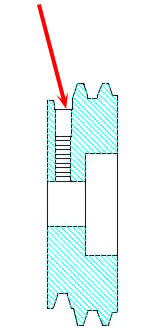
Figure 1-Shows the set screw access hole.
Use a 3/32″ Allen wrench and loosen the set screw about six (6) full turns. Pull the pulley back away from the headstock until you see the flat that is machined into the spindle (see Figure 2). If the set screw has come loose, it may have galled the surface of the spindle, which will raise a bur. This will make the pulley removal difficult. You may need to tap the pulley with a wood mallet or other soft material. Once the pulley is removed, inspect the spindle area around the set screw flat for burs. These can be filed off easily.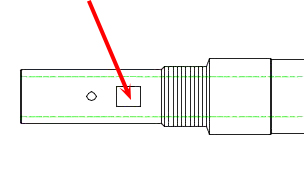
Figure 2: Shows the machined flat
Now push the pulley back on, making sure to align the set screw hole with the flat on the spindle. Push the pulley up until it touches the headstock. Then pull it back until there is a .020″ gap. Now slowly tighten the pulley set screw. As it begins to make contact with the flat, turn the pulley slightly back and forth while holding the spindle stationary (use the Tommy bar to hold the spindle in place).
Continue to tighten the set screw while wiggling the pulley. This will ensure that the set screw is perpendicular to the flat. Once the set screw is set, tighten it. Now spin the pulley a full revolution and see if it is rubbing anywhere (there should still be a .020″ gap). If the gap is there, and there is no contact with the headstock, put the V-belt back on and test it out.
20-25 in/lbs should be sufficient for most work. 30-35 in/lbs, at the maximum. At 30-35 in/lbs, it will be hard to break loose the 10-32 screw that is in the T-nut. The T-nuts will actually start to fail at about 45-50 in/lbs.
One of the slide screw insert nuts on my machine is stripped. Having torn down the machine to the point that I have removed the saddle from the base, I find that the slide screw insert does not contain the leadscrew but can be pulled through it. I have removed the set screw that holds the slide screw insert but cannot determine a way to remove the insert from the saddle. I assumed that with the set screw removed, I could thread in the leadscrew to remove the insert. However, that is not an option with the threads stripped. How do I go about removing this insert and installing a new one?
Click the Instruction link to download the PDF instructions.
Removing the Slide Screw Insert Nut when the Internal Threads Are Gone