|
|
Always wear safety glasses when operating machine tools. |
|
Download PDF Assembly and Instruction Guide
|
|
|
Download PDF DRO Mode Instructions
|
Back to Factory-Installed DRO Lathes
Sale!


17" DRO Lathe with optional accessory package A

17" DRO Lathe with optional accessory package C
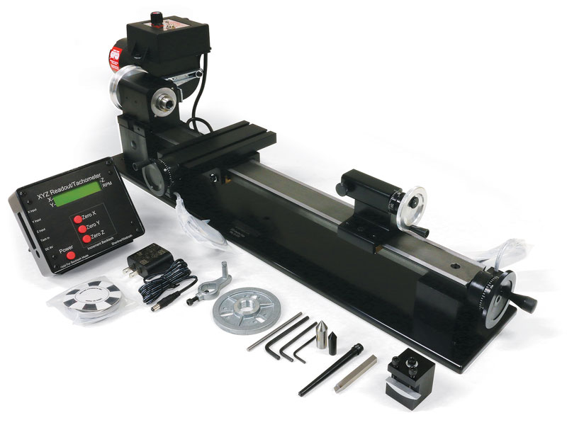
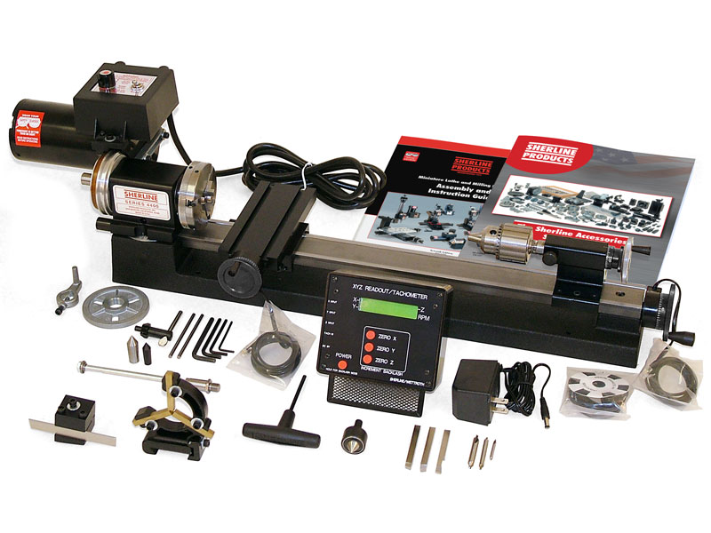
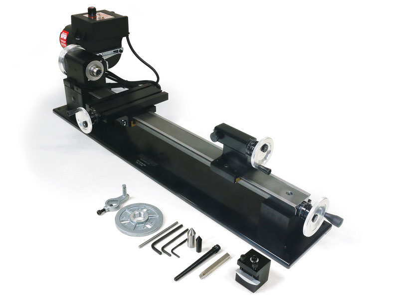
17″ Benchtop Lathe with DRO
Our 17″ DRO Benchtop lathes includes a digital readout box and specialized handwheels with built-in electronic encoders that replace the standard handwheels (standard handwheels are not included with the DRO option). These DRO handwheels interface with the readout box, which translates handwheel movement into precise digital readings for each axis. Each axis can be zeroed at any time with the push of a button, and the DRO continuously displays spindle RPM whenever the motor is running. The readout is compatible with both inch and metric machines.
This compact DRO lathe is ideal for customers who need a small-format machine capable of producing highly accurate, precision parts. Proudly made in the USA, all our lathes are backed by exceptional customer support. Despite its desktop size, this machine delivers full-size performance – capable of cutting wood, plastic, aluminum, and even steel with excellent rigidity and accuracy.
Using the DRO System
The DRO displays each axis position relative to a zero point you set.
- Inch models show position to 0.0005″ (three and a half decimal places)
- Metric models show position to 0.01 mm
The system supports both ball screw and leadscrew machines. As well as the ability to use Metric DROs on inch machines or inch DROs on metric machines. It features six selectable modes based on machine type (mill or lathe), screw type (leadscrew or ball screw), and preferred display units (inch or metric). For setup instructions, refer to the official DRO Mode Instructions.
You can electronically compensate for backlash by inputting the measured backlash value for each axis. When the direction of handwheel rotation reverses, the DRO subtracts the backlash before updating the position – eliminating common errors and making it easier to track travel distance and direction. The power supply automatically switches between 120V and 240V, making it suitable for use in countries with 220–240V electrical current. A socket adapter may be required outside North America.
Features of the 17″ Benchtop Lathe
- 24″ (610 mm) steel bed giving 17″ (431 mm) between centers
- Maximum diameter over bed: 3.50″ (90 mm)
- Crosslide travel: 2.75″ × 6.00″ (70 mm × 152 mm)
- 90 V DC motor with electronic speed control – continuously variable 70–2,800 RPM (no belt changes required)*
- DRO handwheels on leadscrew and crosslide
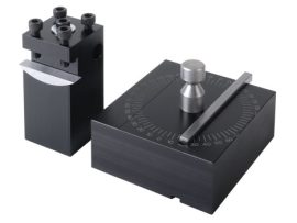
- Rocker-style tool post included
- DRO (Digital Readout) – precise, repeatable positioning, improving accuracy over handwheel-only control
* Not included with lathe without motor and speed control
What’s Included
- DRO readout box, DRO-compatible handwheels / encoder setup
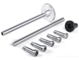
- Pulleys, drive belt, faceplate, lathe dog
- Two dead centers
- Three hex keys
- Rocker tool post
- Sharpened high-speed steel cutting tool
- Grounded 3-wire power cord (8 ft)
- Instruction manual
-


| Swing Over Bed | 3.50″ (90 mm) |
|---|---|
| Swing Over Carriage | 1.75″ (45 mm) |
| Distance Between Centers | 17.00″ (430 mm) |
| Hole Through Spindle | .405″ (10 mm) |
| Spindle Nose Thread | 3/4″-16 T.P.I. |
| Spindle Nose Taper | #1 Morse |
| Spindle Runout of Morse Taper | .0005″ or less |
| Travel of Crosslide | 4.25″ (110 mm) |
| Tailstock Spindle Taper | #0 Morse |
| Protractor Graduations | 0° to 45° by 5° |
| Handwheel Graduations | .001″ (.01 mm) |
| Length Overall | 32.5″ (826 mm) |
| Width Overall | 8.00″ (267 mm) |
| Height Overall | 8.00″ (216 mm) |
| Shipping Weight | 31 lb. (14.1 kg) |
| Motor | 90 volt DC with electronic speed control that accepts any incoming current from 100VAC to 240 VAC, 50 Hz or 60 Hz.
Click here for motor specifications |
| Spindle Speed Range | 70-2800 RPM continuously variable by electronic speed control |
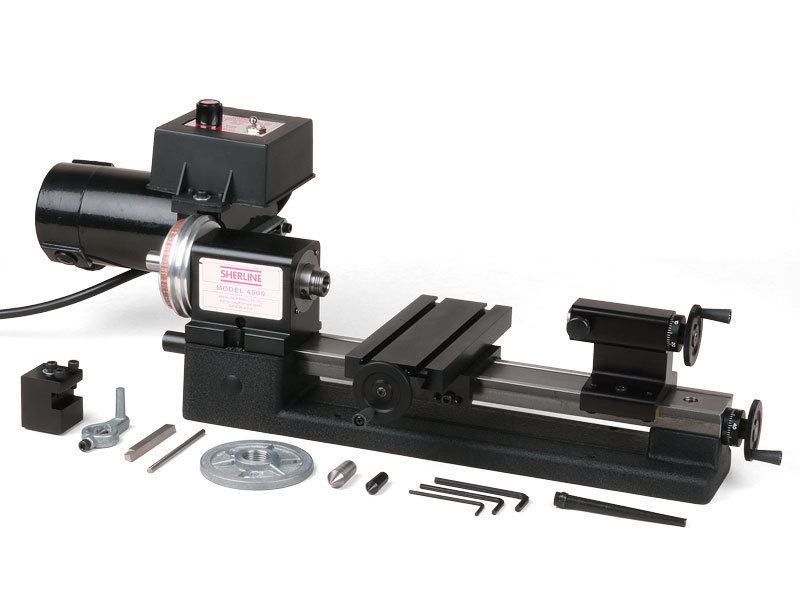
4400-Series Manual Benchtop Lathe-Machined Base
Click on the link for the exploded view of the 4400-Series Manual Benchtop Lathe (2024) to help identify replacement parts.
4400-Series Manual Benchtop Lathe-Cast Base
Click on the link for the exploded view of the 4400-Series Manual Benchtop Lathe to help identify replacement parts.
If you are still uncertain, please call our customer service representatives for help with this item.
 |
 |
|
|---|---|---|
| 4000 (4100) | 4400 (4410) | |
| Swing over bed | 3.50″ (90 mm) | 3.50″ (90 mm) |
| Swing over carriage | 1.75″ (44.5 mm) | 1.75″ (44.5 mm) |
| Distance between centers | 8.00″ (200 mm) | 17.00″ (430 mm) |
| Hole through spindle | .405″ (10 mm) | .405″ (10 mm) |
| Spindle nose thread | 3/4-16 T.P.I. | 3/4-16 T.P.I. |
| Spindle nose taper | #1 Morse | #1 Morse |
| Spindle runout of Morse taper | 0005″ or less | .0005″ or less |
| Travel of crosslide | 4.25″ (110 mm) | 4.25″ (110 mm) |
| Tailstock spindle taper | #0 Morse | #0 Morse |
| Tailstock spindle travel | 1.75″ (44.5 mm) | 1.75″ (44.5 mm) |
| Protractor graduations | 0° to 45° by 5° | 0° to 45° by 5° |
| Handwheel graduations | 001″ (.01 mm) | 001″ (.01 mm) |
| Handwheel type | Standard Handwheels | Zero Adjustable Handwheels (With the exception of DRO machines, which come with DRO handwheels) |
| Electronically controlled spindle speed range | 70 to 2,800 RPM | 70 to 2,800 RPM |
| Length overall | 23″ (584 mm) | 32.5″ (826 mm) |
| Width overall | 10.25″ (260 mm) | 10.55″ (267 mm) |
| Height overall | 8″ (203 mm) | 8.5″ (216 mm) |
| Shipping weight | 24 lb. (10.9 kg) | 30 lb. (13.6 kg) |
| Motor Specs | ||
| Input voltage | 100 to 240 VAC, 50 or 60 Hz | |
| Output to motor | 90 VDC | |
| Current draw | .5 to 15 amps, depending on the load | |
| No-load output shaft speed | 6000 RPM (no pulley) | |
| Click here for more detailed specs | ||
| Spindle Specs | ||
| Spindle End play (factory adjustment of preload) |
.0002″ (.005 mm) or less, normal pulleys | |
| Runout at nose | .0005″ (0.013 mm) or less | |
| Bearings | Two 20 mm lifetime lubricated ball bearings with adjustable preload | |
Related products
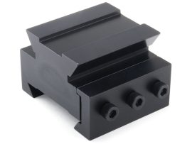
Headstock Riser Block Set
The standard Sherline lathe can accommodate parts up to 3.5" (90 mm) in diameter. However, there are times when you may need to work on larger pieces. The Sherline headstock spacer block increases the lathe’s maximum working diameter to 6" (152 mm), significantly expanding its capabilities.
This set includes a 1.235" (31.37 mm) spacer block that fits beneath the headstock, along with a riser-rocker tool post to elevate the cutting tool accordingly. If you plan to turn parts between centers while using the headstock riser, you’ll also need a tailstock riser block to maintain proper alignment.
Note: Although the spacer block allows turning parts up to 6" in diameter, the lathe’s motor power remains unchanged. This accessory is best suited for machining easy-to-cut materials or for occasional use when extra clearance is needed. If your work frequently requires this added capacity, upgrading to a larger lathe may be advisable.
Tailstock Riser Block
For those customers interested in turning larger diameters between centers, the Tailstock Riser Block will raise the tailstock to correspond with the riser block kit, allowing you an additional 1.235" (31.37 mm) of clearance. The Tailstock Riser Block has a two-part dovetailed base to allow for easy installation and secure locking to the bed.
$119.40
Select options
This product has multiple variants. The options may be chosen on the product page