CNC Projects Built Using Sherline Tools
Shown on this page are projects Sherline owners have built using Computer Numeric Control (CNC) on their machines. As CNC has become a major force in commercial machine shops in the past decade, it is also becoming more popular in the home shop as well. This is driven by the lower-cost systems now available, the greater public knowledge of what can be done with CNC, and by the increased number of machinists that already know how to use CNC machines at work. We offer these projects as examples of what people have actually done with their machines. We get questions all the time asking, “Can CNC do this or that?” We feel that seeing actual results is much more informative than listing stepper motor resolution figures, backlash amounts or other statistics that might look good on paper but don’t give you a real-world feeling for what you could actually do if you had such a machine. Keep in mind also that the projects shown here are not the limits of what can be done with CNC, just some examples of what has actually been done so far.
Send Us Photos of Your Projects
We hope you enjoy these projects, and if you have made something on a Sherline CNC machine that you would like to share here, please contact us and send photos and a description to be added to this page. If you would like to share the actual G-code you used to make the part, that will make the page even more valuable to those wishing to follow in your footsteps. The ideal submission would have a photo of some of the key setups, tooling used, a shot of the finished part, the G-code used, and a description of any special problems that had to be solved to make the part. Readers would also probably be interested to know if the G-code was written from scratch or translated from a CAD file, and, if so, which one and what translator program was used.
You may send your suggestions to us by mail, fax or email as follows:
Mail: Attn: Kat, Sherline Products Inc, 3235 Executive Ridge, Vista, CA 92081-8527, USA.
Email: kat@sherline.com
Table of Contents
- “Baby Beam” steam engine model by Alan Marconette
- A spindle drawbar remover by Colin Dyckes
- A machinist’s puzzle—A cube within a cube within a cube by Tom Hubin
- A CNC church in two parts by Tom Hubin
- Cutting a helical gear by Joe Martin
- a. Counterweight the mill Z-axis by Harry Yingst
b. A spring counter-balance for the mill Z-axis by Stan Figora - Keeping chips off your Y-axis leadscrew from Tim Schroeder (A tip rather than a project…)
- A minibike supercharger by Robert Rosenfield
- A humanoid robot by Matt Bauer
- A handwheel in place of a stepper motor on CNC-ready tools by Stan Figora
- A tip on lathe cutting direction plus more tooling tips by William Bassett
- Grinding a cam for a model V4 engine by Joe Martin
- A rapid advance manual handwheel adapter made using CNC by Joe Katona
- Making a set of CNC box wrenches by Joe Peitz
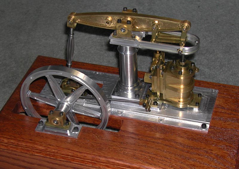
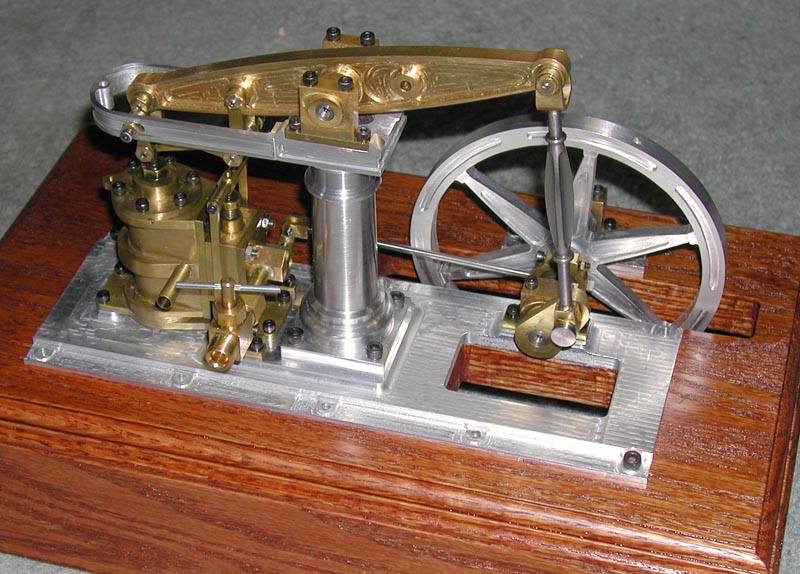
1. “Baby Beam” Steam Engine Model by Alan Marconette
Two views of Alan’s “Baby Beam” steam engine. Click on any photo to view a larger image.
The “Baby Beam” Steam Engine is almost finished. No, the final engine will not have SHCS (socket head cap screws)! It was inspired by the M.E. Beam engine published in ‘59, which was scaled from the 1914 M.E. article by George Gentry. George did an accurate prototype model of the engine. I’ve heard that it is of the form of engines designed by William Fairburn in the 1840-1850 period.
The engine is approximately 6″ tall, 11″ wide and 6″ deep. Shown is a 5″ CNC’d flywheel, and the plans include an optional 6″ flywheel of an alternate design. This engine was built using many CNC part files and was entirely machined on the Sherline mill and lathe. This version was built with a brass cylinder, steam chest, and beam, although aluminum could be used as well. The base is aluminum and, although 10″ long, was machined on the Sherline mill as well!
The bore is 3/4″, and the stroke is 1 1/2″. The design incorporates a slide valve driven through considerable linkage. The piston drives the 6-1/2″ beam through the Watts parallel motion and is a joy to watch.
Alan Marconett KM6VV
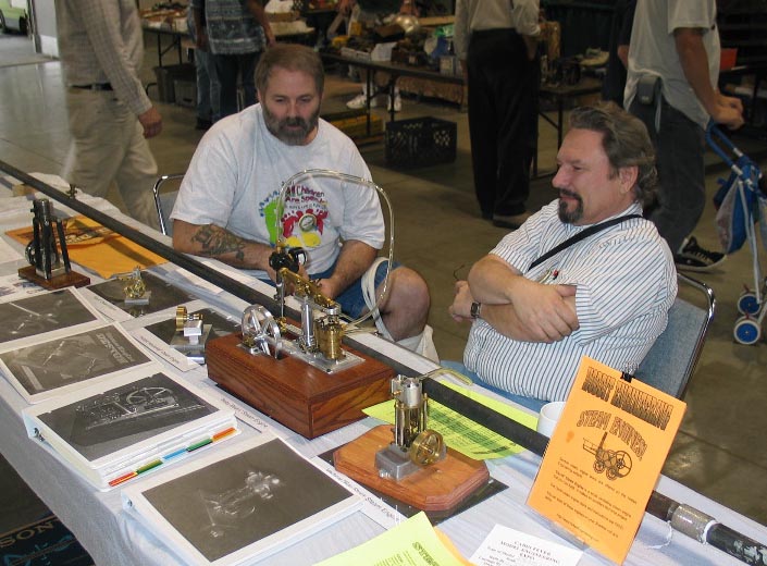
Alan (Right) shows his engine at the 2004 Men, Metal and Machines show in Visalia.
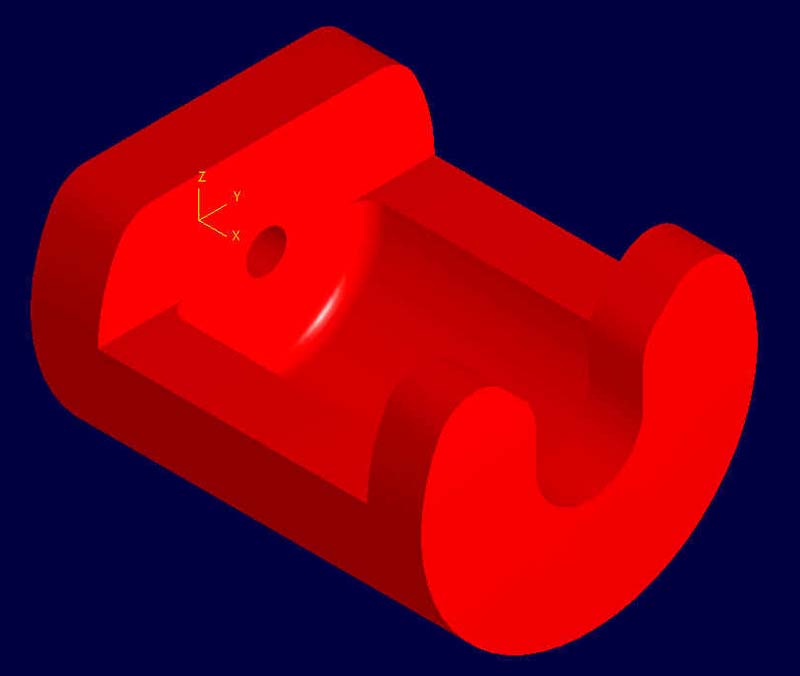

2. A CNC-machined spindle drawbar remover by Colin Dyckes
The 3D CAD drawing and the photos on the left help explain how the puller is made. Click on any photo to view a larger image.
Colin didn’t send any written explanation when he attached these photos to his e-mail, but the photos pretty much speak for themselves. This part offers another take on the best way to remove a collet or chuck from the spindle without hammering on the drawbolt. Any method that uses slow, constant pressure to push the arbor out of the #1 Morse taper in the spindle helps keep your machine in alignment and saves the Z-axis from developing excess backlash from the handwheel set screw having to support the force of pounding on the headstock.
To use the puller, a split collar is attached to the spindle shaft leaving enough space underneath to insert the base of the puller. To remove the item from the spindle taper, the drawbolt is first loosened. Then the puller is inserted under the collar, and the socket head screw is tightened against the head of the drawbolt. Tightening the screw pushes down on the bolt, removing the tapered collet or arbor from the spindle.
After seeing this write-up, Colin mentioned that after trying his first prototype, he ended up filing a groove in the spindle shaft while it was spinning. It doesn’t show in the photos, but the set screw in the split collar goes into this groove. This helps keep the collar from slipping up on the spindle shaft when the screw is tightened against the drawbolt head. He says this is optional.
For those who would like 3D and CNC files for the puller, Colin’s drawings are included as the following links (both are supplied in a single .zip archive): .STL file or .IGS file
Colin adds: “The IGES file (.igs) and the Stereo Lithography file (.stl) should be readable by just about any CAM program (VisualMill, SurfCam, Solidcam, etc., etc.). I supplied those files rather than the original Solidworks file because they are pretty much universally readable. The STL or IGES files will need to be rotated within the CAM package to get the correct orientation for milling.”
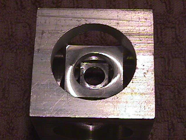
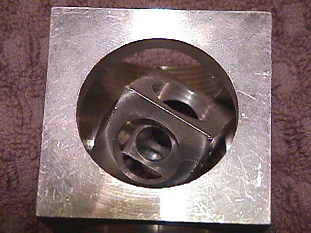
3. A machinist’s puzzle—CNC nested cubes by Tom Hubin
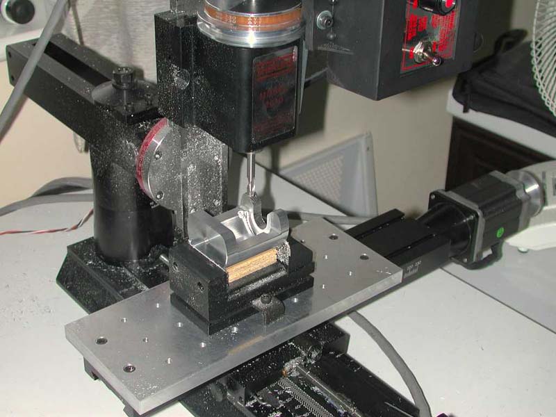
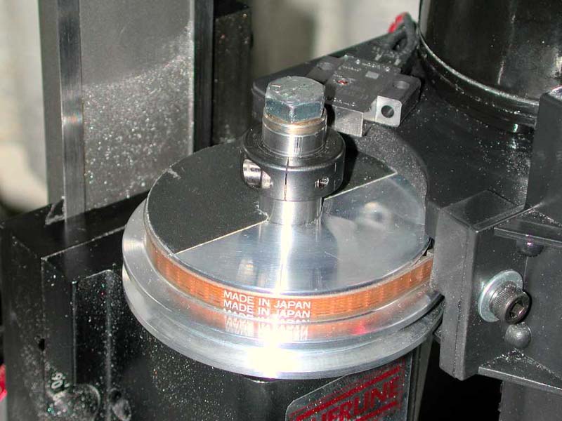
The photos above show various stages of the machining of the puzzle. It is simply a number of accurate boring jobs in a row. Click on any photo to view a larger image.
This is a project done on my Sherline 5410 mill using TurboCnc 3.1a.
Directions for using g-code file 3cubes.cnc to machine 3 nested cubes. (File: 3cubes.txt copyright Tom Hubin, 26 November 2004)
- Start with a 2-inch cube of 6061 aluminum. This can be a 2-inch length cut from 2-inch square bar stock.
- Mill or fly cut the outermost 1.950-inch cube from the 2-inch stock. Be sure to machine something from all six sides so that the finish is attractive.
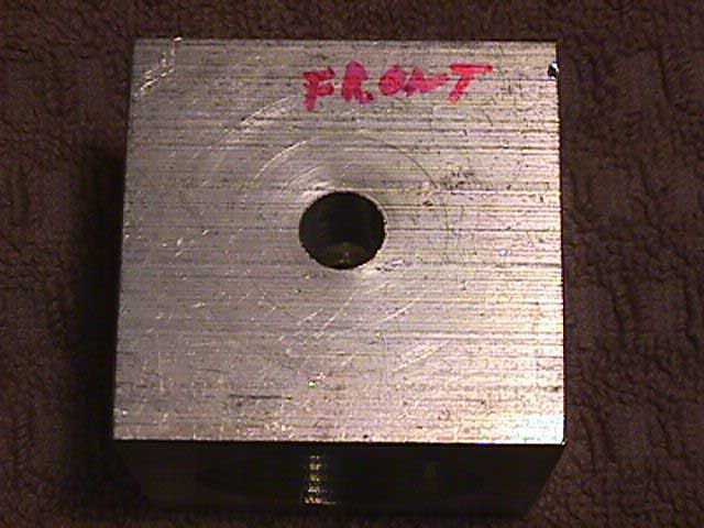
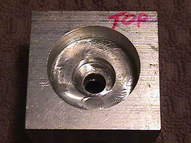
- Label the six sides as top, bottom, right, left, front, and rear.
- Drill 3/8 inch diameter center holes into the top, front, and right surfaces to a depth of 1.5 inches. These three holes will pass completely through the innermost cube. I used the 3/8 inch end mill holder with a machine screw length 3/8 inch diameter drill bit.
- Drill 3/8 inch diameter center holes into the bottom, rear, and left surfaces to a depth of 0.75 inches. These three holes will not touch the inside of the innermost cube. That way, the 3/8 inch diameter center holes through the innermost cube will be seamless.
- Secure the 1.950-inch cube in a vise and use an edge finder to accurately locate the rightmost surface and the rearmost surface so that the center of the topmost surface is at (X,Y)=(0,0).
- Load a 3/8 inch diameter x 5/8 inch LOC aluminum roughing end mill. Move it over the topmost surface. Lower the bit until it just touches the topmost surface. I usually do this by loosening the bit so that it drops down and touches the topmost surface. Then tighten the bit just enough so that it won’t fall out.
- Run the program. You will be prompted to touch the surface with the end mill. You have already done this, so continue.
- The bit will be raised, and you will be prompted to tighten the bit and start the spindle at 2800 RPM, which is the max spindle speed on a Sherline mill. Tighten the bit securely, then start the spindle.
- Stay near the machine, lubricating and clearing chips as machining takes place.
CLICK HERE to download the ZIP file that contains the following original files:
- 3CUBES.CPP (3cubes.cpp is a plain text Borland c program to generate the g-code file.)
- 3CUBES.OBJ
- 3CUBES.PRJ
- 3CUBES.BAK
- 3CUBES.EXE
- 3CUBES.DSK
- 3 CUBES.NC (3 cubes.nc is plain text g-code for TurboCnc 4.01.)
The remaining 3cubes.* files are binary files generated by the Borland C++ compiler but are not needed.
*.txt, *.cnc, and *.cpp are plain text files and can be read and modified with just about any DOS, Linux, or Windows text editor. DOS Edit command can be used. I use the shareware DOS text editor PcWrite. Microsoft Notepad, WordPad and Word are Windows text editors that can be used.
Here are some websites to help visualize the nested cubes:
www.dakeng.com/gallery.html—Dan Statman’s dime-sized nested cubes. Small and very, very classy.
Tom Hubin
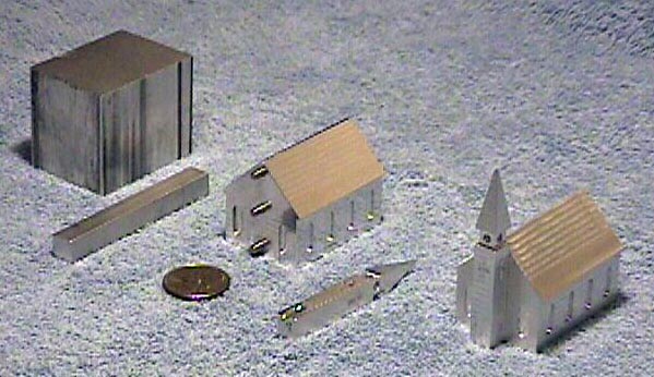
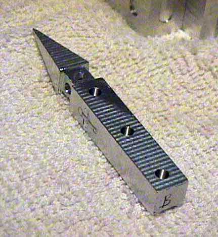
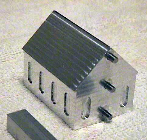

4. A CNC church in two parts by Tom Hubin
This project is an excellent example of how a number of CNC files and fixtures are used to handle all the various operations involved in making a multi-sided part. It’s not simply a matter of one G-code file that does everything. The files can be found by downloading the ZIP file linked in the paragraph below. Click on any photo to view a larger image.
DRAWINGS
This church is machined completely using CNC. It is made it two pieces—the church and the steeple—that go together with pins. The dimensioned drawings were done in a program called “Vellum.” They have a .VLM file extension and can be viewed by downloading a free utility called “Vellum Share,” which you can obtain at www.ashlar.com/products/share. There are versions for Windows and Macintosh. In some cases, the drawings also show the holding fixtures. The drawing files can be found in the Zip file linked below.
G-CODE
I ran the G-code with TurboCnc 3.1a on my Sherline 5410 mill. After designing and making the jigs, I made a batch of 8 churches for Christmas 2003. I started the project in early November 2003 and finished in March 2004. A few months late for Christmas but well received nevertheless. Machining and handling time for the building and the steeple is about 6 hours each when done in a batch of 8. That is about 12 hours per church. The project was inspired by one page of a Home Shop Machinist magazine article that was sent to me by an acquaintance. The files needed to make the parts can be obtained by clicking on the file name CHURCH.ZIP to download a 354 Kb Zip file. One of the zipped files is called “SEQUENCE.TXT.” This file will explain the order in which the other files are run and what they do.
CLICK HERE to open the CHURCH.ZIP files
Designed by Tom Hubin Nov 2003.
Copyright Tom Hubin, 2003 and 2004.
Tom Hubin
An interesting side note about the church project…
Neil Knopf of The Home Shop Machinist Magazine adds the following note about the original article on the church project:
“The church was run in the September/October 2002 issue of HSM. It was designed by Walter Yetman of New Jersey and close friend Rudy Kouhoupt. Walter made the church as a gift to his pastor and dedicated the article to his friend Todd Beamer who was Walter’s son’s Sunday school instructor. Todd was killed in the 9/11 crash of Flight 93 in Pennsylvania. He was the one who declared, “Lets roll,” as he and a few others went forth to overwhelm the terrorists.”
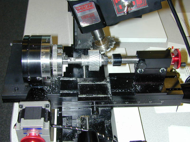
5. Cutting a Helical Gear by Joe Martin
The setup on a Sherline mill. Click on photo to view a larger image.
Actually, cutting a helical gear is an easy task for a CNC machine. It’s figuring out the math to write the G-code that is the difficult part. Joe Martin designed a helical gear to cut as a CNC demonstration at a trade show, but to do so, he ended up writing a program to help figure out the variables.
Here, we have used a number of Sherline accessories. The 3701 right-angle attachment holds the rotary table vertically, while the 3702 right-angle adjustable tailstock holds a P/N 1191 live center to support the other end of the arbor that the gear blank is attached to. The 3701 and 3702 each sit on top of a P/N 3017 crosslide accessory plate to get a little extra height. A P/N 3231 Gear cutter arbor holds an involute gear cutter on the spindle, which is offset to the appropriate angle. The X-axis moves left/right and the A (rotary) axis indexes for each tooth and rotates as the blank is fed past the fixed spinning cutter. The Y-axis is used manually to adjust the tooth depth or with CNC to cut the gear to the proper depth in a number of passes if needed. (This gear in aluminum could be cut to full depth in one pass.) The Z axis does not move.
Making the Calculations
In order to help with the calculations on a helical gear, Joe Martin wrote a Microsoft Excel® program that helps come up with the unknowns when you have the necessary pitch and angle information. Viewing this program requires Microsoft Excel. To view the formulas that Joe developed to make the calculations, you will first have to unprotect the worksheet by going to the “Tools” menu and selecting “Protection>Unprotect.” Then, when you click on one of the cells that contain a formula, you can read the formula in the window above the worksheet. When you are done looking, be sure to remember to protect the file again. Understanding these formulas will require a pretty good working knowledge of Microsoft Excel formulas. Using the sheet just requires that you know the values to plug into the pink cells. When you change one of those numbers, the formulas will recalculate the values in the orange cells for you. Once you have the values, there is another function included that will write the g-code for you. This clever addition to the program was written by Bill Krobetzcy and his future son-in-law Jeremy.
CLICK HERE to download Joe’s Excel Program to develop the values for a helical gear.
The G-Code
Once you have the numbers, writing the program is fairly easy. It is a set of five lines of code repeated by the number of gear teeth. Notice that dimensions and angles are given to four decimal places. In this case, the 34-tooth program begins…
%
g90g01x0.0y0.0a0.0f15.0
g90g01a0.0f15.0
g90 g01 y-.0895 f5.0
g91x-1.70a-47.0310
g90g01y.05f15.0
g91x1.70a47.0310
g90g00a-10.5882
g90 g01 y-.0895 f5.0
g91x-1.70a-47.0310
g90g01y.05f15.0
g91x1.70a47.0310
g90g00a-21.1765
g90 g01 y-.0895 f5.0
g91x-1.70a-47.0310
g90g01y.05f15.0
g91x1.70a47.0310
g90g00a-31.7647
And so on to the last block:
g90 g01 y-.0895 f5.0
g91x-1.70a-47.0310
g90g01y.05f15.0
g91x1.70a47.0310
g90g01a0.0f720.0
%
As you can see, once started only the last number changes in each block of code as it indexes for the next cut. To get the entire 34-tooth program in .txt format, CLICK HERE to download the .zip file.
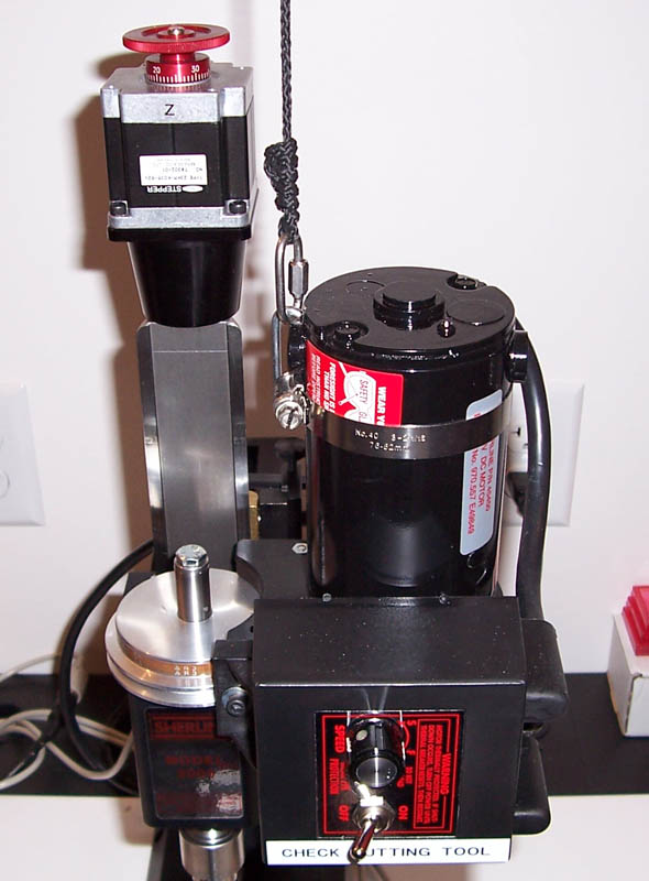
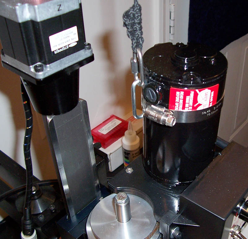
6a. Counter-weighting the mill Z-axis by Harry Yingst
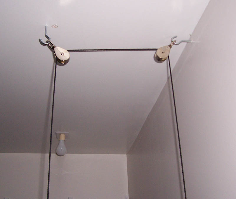
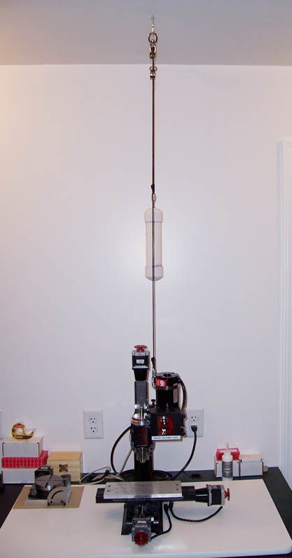
Photos of the counterweight system show how it is attached to the mill DC motor using a hose clamp and how the line runs through pulleys attached to the ceiling to keep the weight out of the way. Click on any of the photos to view a larger image.
While not actually a project you can do WITH your CNC mill, here is a project you can do TO your CNC mill for better response on the Z-axis. One of the problems with a vertical mill, unless you happen to be working in outer space is that gravity makes it a lot easier to lower the Z-axis than to raise it. The stepper motor must raise the entire weight of the saddle, headstock, speed control, motor, and cutting tool each time it goes up. One way they alleviate this problem on big machines is to use a counterweight that effectively neutralizes the weight of the head so that it takes the same amount of effort to raise or lower it. The Sherline headstock/motor unit weighs about 10 pounds, which can be a lot for a 136 oz-in stepper motor to lift, particularly in 3D projects where there might be a lot of small, rapid up/down movements of the Z-axis. Harry Yingst submitted these photos of a system he came up with using a lead shot-filled tube and a pulley system suspended from the ceiling. You can probably think of some other ways too, but here is one that uses few parts, requires no holes to be drilled in the machine, and uses easy-to-find materials you may already have lying around.
Here is what Harry had to say when he sent in the above photos:
Attached you will find some photos of my counterweight setup. The weight itself is a 9.5” piece of 2” PVC pipe and end caps. I drilled a hole in the center of the top one to put a screw eye through and used a fender washer and a lock nut on the inside and a standard nut on the outside. I filled the counterweight with #8 lead shot and glued it all together. (I still need to paint it.)
I used a piece of Dacron rope and connected the weight to the mill using a 3” hose clamp and a single link of chain as an attachment point. You will notice in the picture that I used a screw-on type chain link on both ends of the line to allow the weight to be easily removed or changed if desired. I may make a second weight someday as I am considering making a second high-speed milling head (30,000 rpm or more) for use in engraving PC boards, so I want to be able to swap weights quickly.
—Harry Yingst
6b. A spring counter-balance for the mill Z-axis by Stan Figora
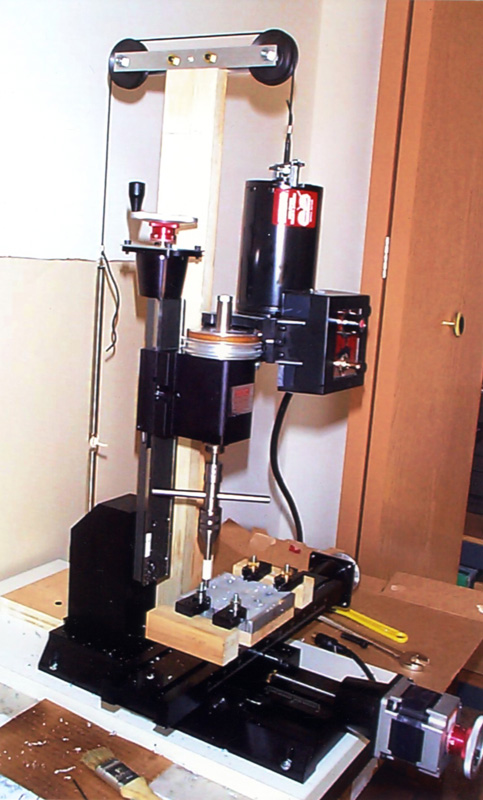
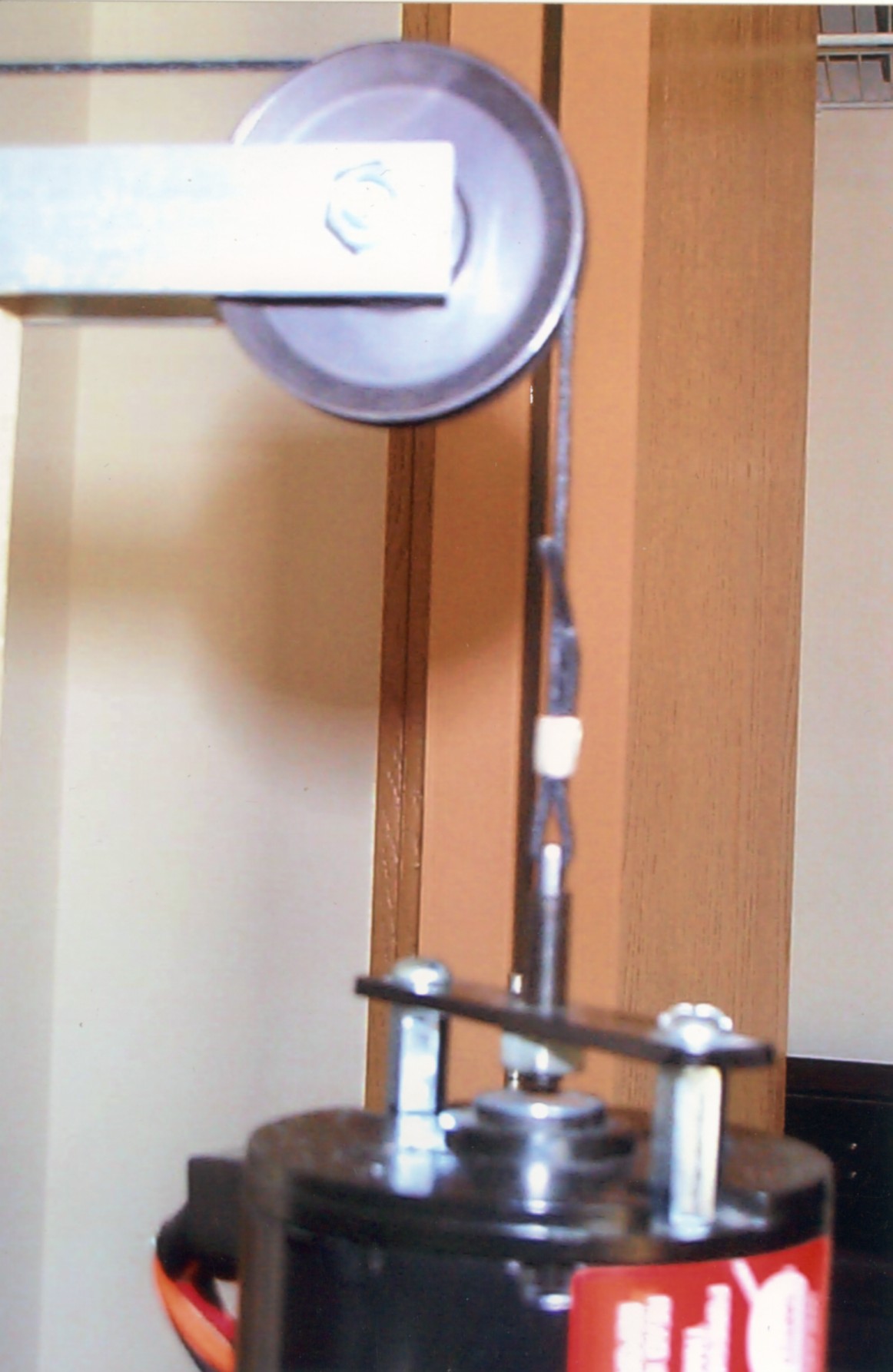
Shown here is Stan Figora’s spring tension system to counter the weight of the headstock, motor and speed control on the mill’s Z-axis. Being attached to the machine base, it moves with the machine and requires no permanent ceiling-mounted components. Stan is also working on a lead weight system to replace the springs. The weight will be guided to roll between vertical brass rods. Click on either photo for a larger view.
Stan Figora has approached the counter-weighting problem a little differently and come up with a self-contained solution that doesn’t require attachment to the ceiling. His first “temporary” solution is shown above, where he uses two springs in series attached to a 1/16” diameter boot lace. The lace runs over two pulleys attached to a wooden support column and down to a fixture attached to the motor with two standoffs. Stan also noted that McMaster-Carr offers a 1/16” diameter polyester dial cord would be an upgrade to this solution. Another choice was .035” nylon coated miniature steel cable (90 pound rating) that was used in some older test equipment, but he decided to keep this one as simple as possible.
Stan is now working on a more sophisticated weighted system that will feature ball-bearing closet door rollers attached between two lead weights. The four rollers within the weight will run up and down guided by two vertical brass rods mounted behind the mill base. If he sends photos, we will included them here.
7. Keeping chips off your Y-axis leadscrew from Tim Schroeder
Tim Schroeder’s solution uses flexible rubber tire inner tube material along with some custom brass angle pieces to keep chips off the Y-axis leadscrew. Click on photo for a larger view.
The X and Z leadscrews on a Sherline mill are positioned so that they are protected from flying chips. The Y-axis screw, however, is exposed. On a manual mill, the operator is in constant attendance and can simply brush the chips away periodically, but CNC operations often run unattended for periods of time, and the volume of chips produced with a CNC system can make finding a way to keep them off the Y-axis screw a higher priority. Tim Schroeder came up with a pretty good solution for his manual machine by using some old rubber inner tube material which is held in place with brass angle that attaches to the mill base and front of the saddle. A second piece is located behind the table and is secured to the front of the mill column base. The above photo is pretty much self-explanatory as to how it works. The addition of these parts may mean a slight reduction in your Y-axis travel, but in most cases, the extreme ends of your travel envelope are not used anyway.
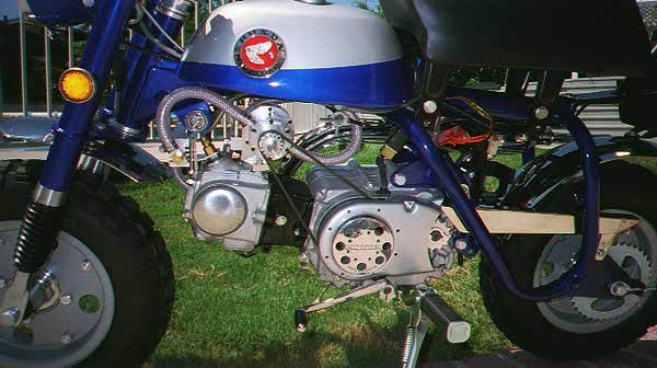
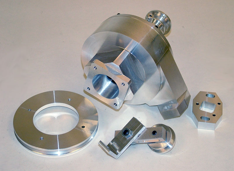
8. Supercharger for a Minibike by Robert Rosenfield
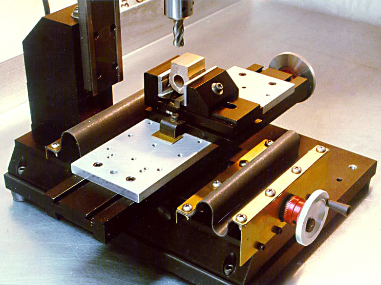
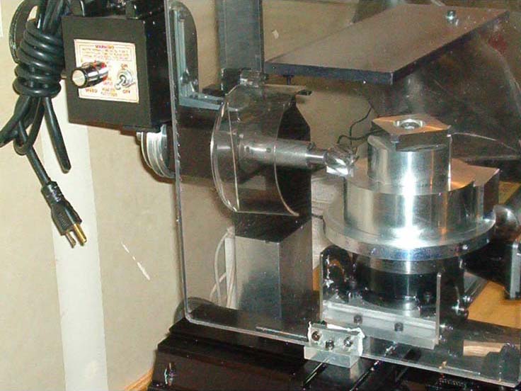
Robert Rosenfield recently completed a supercharger for a restored 1960s Honda 50 mini trail bike. The parts for the supercharger body were mostly cut on a manual Sherline mill, but the turbine itself was cut using CNC on the Sherline mill. Click on any photo to view a larger image.
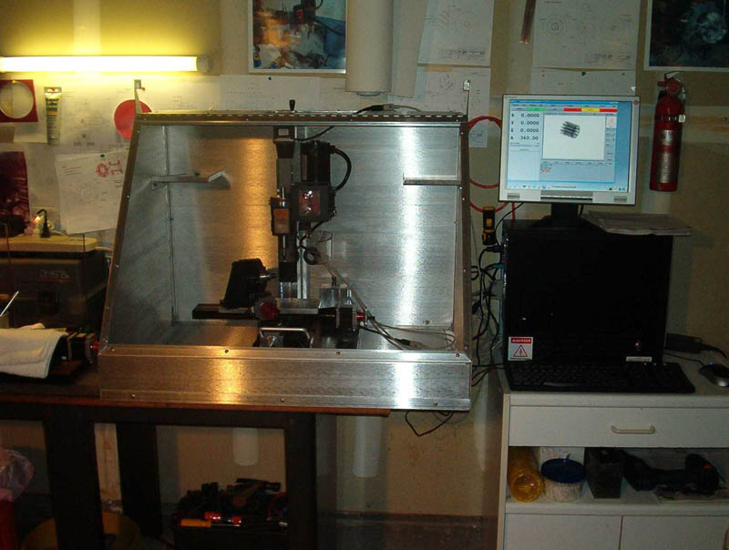
The Honda Trail 50 minibike fitted with the custom supercharger makes more horsepower. Also shown is Robert’s shop with the sheet metal enclosure for the mill.
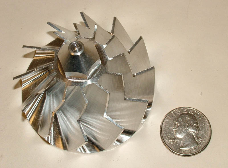
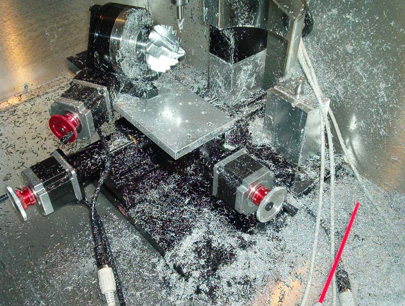
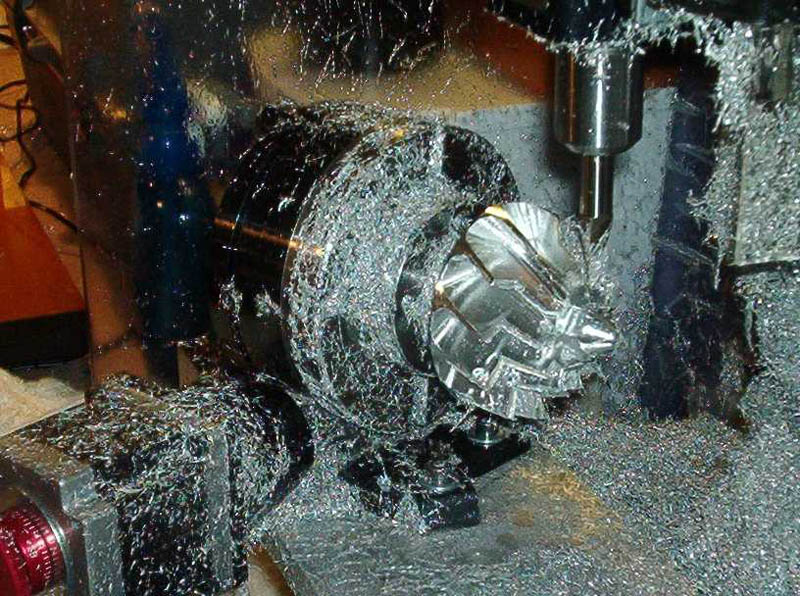
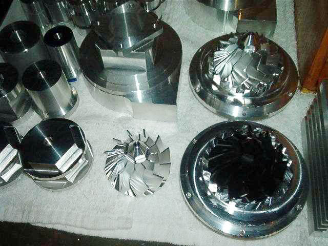
The photos show the horizontal mill setup used to cut the round parts on a rotary table. The second photo shows the rotary table offset at an angle on a tooling plate so that the turbine blades can be cut. The third photo shows the 10° tapered 3/8″ end mill making the cuts. The 4th photo shows the finished turbine and some other parts in aluminum and Delrin.
The blades shown in these photos were made with a straight cut. Robert has made later models where the tool path is a curve rather than straight, as he feels this should achieve better air movement as well as make for a more impressive-looking part.
To view a dimensional drawing of the turbine in PDF format, CLICK HERE. Drawings of each of the other parts are also available upon request.

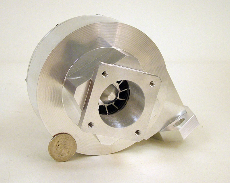
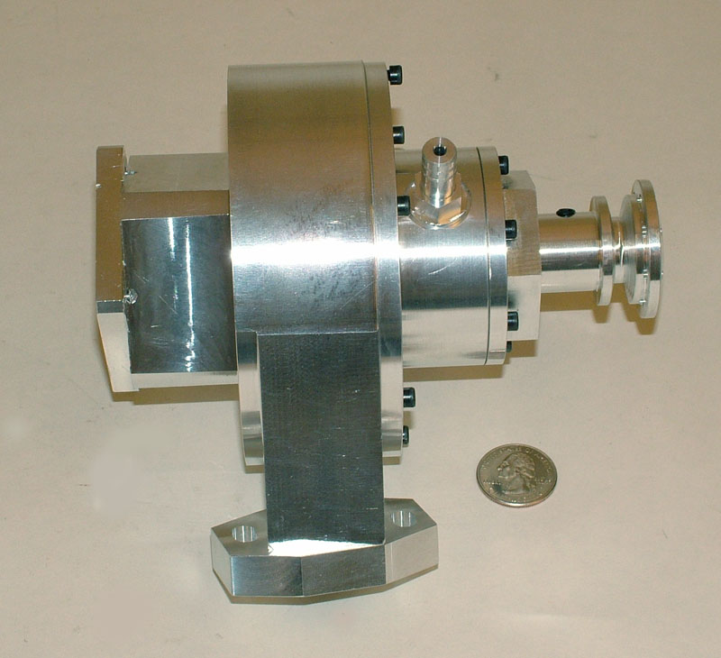
A New Version
Robert’s latest compact supercharger design for small motors. (Telephone for size comparison in first photo, a 25¢ US coin in final two photos.)
According to Robert, “These are the brand new Model SC125 superchargers designed for 50 cc thru 125 cc four-stroke motors used in pit bikes, super pocket bikes, go-karts, Honda ’50s, etc.”
Overall dimensions are: 4-1/2″ O.D. x 5-1/2″ tall x 4-3/4″ wide. Original 63 mm (2-1/2″) 30º blade with a left-hand thread. Design capabilities include 2-1 pressure ratio variable boost, maximum 100,000 RPM shaft speed, and 24-34 mm carburetor sizing. Pressure oil feed to plain bronze bearings with VitonT seals for high temperatures.
As usual, the photos show that Robert has also been able to obtain really nice finishes with his manual and CNC Sherline machines. The main body is made from one large billet of aluminum. It can take several days of machining time to get it down to size. Although this could be done quicker on a larger, more powerful machine, it is interesting to note that the hobbyist with time and talent but limited funds and space can still achieve superb results with tabletop machine tools.
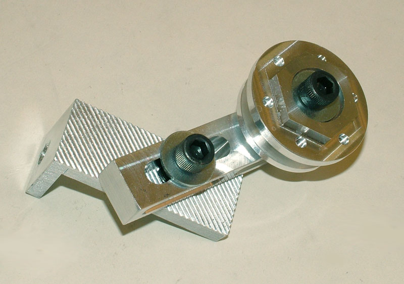
(Last photo) Here is an adjustable pulley tensioner assembly made by Robert, again with beautiful finishes.
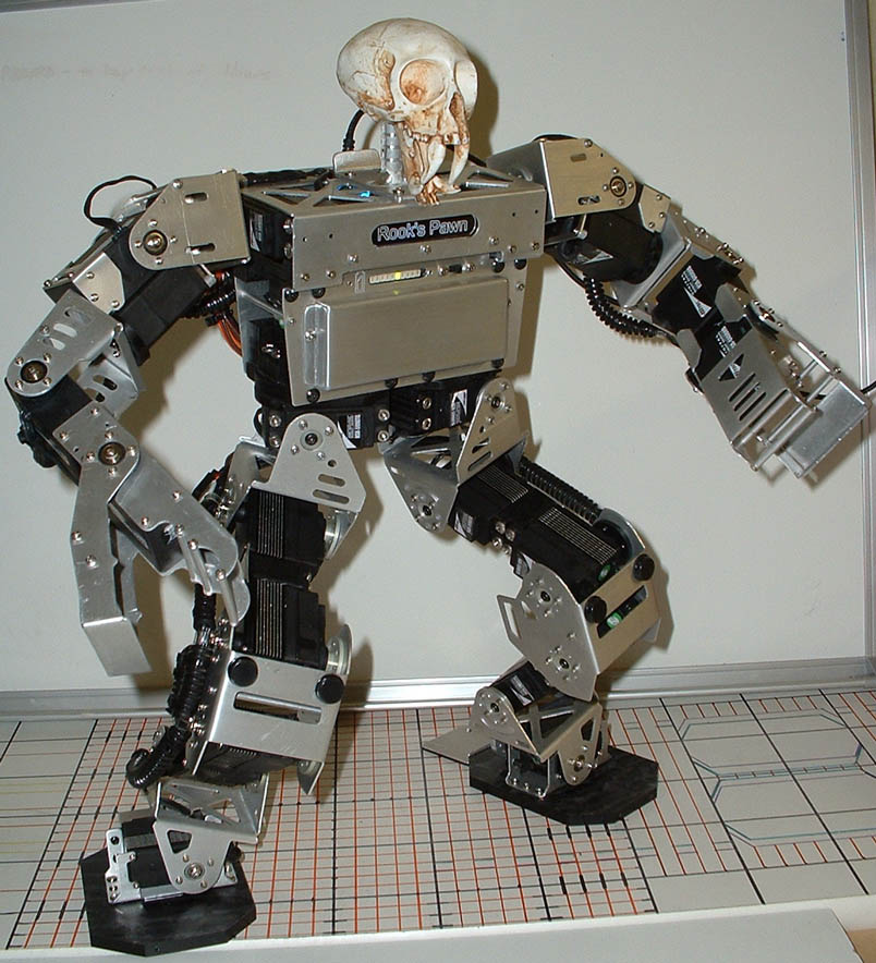
9. A Humanoid Robot by Matt Bauer
Matt Bauer found that CNC made many aspects of building the parts for this robot much easier. Not bad for a first project in CNC. The sabertooth skull is a nice touch. Click on photo to view a larger image.
Matt Bauer was not a machinist and had never worked with CNC when he purchased a Sherline CNC mill and a lathe. It didn’t take him long to get the hang of it, and the robot shown in the picture was his first project. He describes the process best in his own words:
“Shortly after our return from the ROBO-ONE 10 competition in Japan last Fall, I purchased the Sherline model 2010 CNC Mill and 4410 CNC Lathe. Having no previous CNC experience, I was surprised by how fast I was able to learn the necessary techniques needed to operate the machines. No longer than a week into it, I decided to scrap our previous robot design entirely. Before that, I was forced to fabricate all the aluminum brackets using a band-saw and drill. The parts created for a humanoid robot are mostly mirror images of its other half, so the CNC capabilities of your machines allowed me to easily duplicate opposing sides and make short work of the intricate designs I was ultimately going for. In a nutshell, this 24 servo humanoid robot consists of 45 aluminum; and 27 delrin parts all done using the Sherline mill and lathe. I was even able to add a little flare by engraving his name in an acrylic backlit marquee located on his chest. Pictures say a thousand words, so here is a pic of our completed humanoid robot dubbed “Rook’s Pawn III”. He stands 19″ tall and weighs about 5.0 lbs. He will be attending RoboGames very soon, and we plan on returning to Japan in the Spring to compete against some of the best humanoids in the world. Thank you.”
10. A handwheel in place of a stepper motor on CNC-ready tools by Stan Figora
This photo shows Stan’s solution to a way to operate a Sherline CNC axis manually when a stepper motor is not available or needed. Click on photo to view a larger image.
Stan Figora had a CNC-ready Sherline mill for which he only needed CNC control on the X and Y axes. He figured, “Why buy a $75 stepper motor for the Z-axis when all I need is a little up/down positioning control now and then?” When ordering Sherline tools “CNC-ready,” it should be noted that they cannot be operated manually until stepper motors with a through shaft are mounted. Some customers know they will eventually want to use their tools using CNC but would like to learn to use the tools manually first. At present, the only alternatives are to either purchase manual tools and convert them to CNC later or to purchase CNC-ready tools and add stepper motors to each axis so that you can attach handwheels to the rear shafts.
Stan got around that limitation by machining a simple aluminum plate that attaches to the stepper motor mount. He fitted a brass bushing in the center hole and made a short 1/4″ diameter shaft to go between the shaft coupling inside the housing and the handwheel. Because the bushing raised the handwheel collar above the surface of the plate, he attached a small piece of aluminum in which he scribed the zero reference witness mark.
11. A tip on lathe cutting direction by William Bassett
“We had a CNC shop for many years. One item required using 35° inserts for profiling, including machining up to a shoulder. We had a problem with breakage. Every machinist learns to feed a bit from the tailstock toward the headstock. We reasoned that as the insert curled a chip, that chip would get caught between the insert and the shoulder of the part, thereby breaking the tip of the delicate insert. The solution was obvious—reverse the feed direction. Machine the shoulder first and then feed toward the tailstock. The inserts lasted much longer. As a bonus, we discovered that we had much better surface finishes. The geometry of the cut was such that the lead angle of the insert in the direction of cut curled the chip away from the just-cut surface. We also obtained a better finish on the shoulder by programming a depth of cut equal to the tool tip radius. The tip radius gave us a pseudo lead angle.”
Some additional thoughts on tooling from an expert
“END MILLS—End mills are not designed to work as drills. Because they cut sideways, they must be strong. This means that compared to drills, they are built short and stubby. This also means there is not as much space left for chips to clear and coolant to get to the cutting edges. The edges at the very center of an end mill do not form chips well. If you plunge an end mill directly into metal, a sort of work-hardened wad forms at the center that somehow has to mush through metal.
CENTER-CUTTING END MILLS—A better way to get down to depth is to slide down on a ramp if the pocket is rectangular. If the pocket is circular, or if you prefer, program a helix or spiral to get down to depth. This way, the end mill cuts on the outer edges, the way it was designed to cut. Some end mills are even made with a hole at the center where cutting edges would otherwise be. It is easier to sharpen these end mills if you do not have to worry about center cutting. Such end mills are often cheaper to buy.
NUMBER OF FLUTES—As long as we are on the subject, use four-flute end mills if you cut tougher or harder materials. The end mills are stronger and stiffer, and they have more cutting edges meaning they can be fed at twice the inches per minute for the same chip load per tooth. The downside is there is less room to clear chips and allow coolant in. Use two-fluted end mills for aluminum because there is more room for chip clearance and less need for strength. Studies have shown that there is no real limit to the speed at which you can cut aluminum. The only limitations are the rigidity and horsepower of the machine and the ability of the end mill material to absorb heat. Do not test this theory on Sherline machines because you can burn out the spindle and stall the stepper motors.
AVOIDING CHATTER—If chatter is a problem, it is good to reduce speed and increase feed, as noted in the Sherline literature. For milling, however, there is another choice that may help. End mills with a high helix angle are less prone to chatter. Here is an exercise that shows what is happening. Drag the edge of a card across a flat surface, and it will chatter. However, if you drag a pencil or pen across the same surface, it will glide smoothly. A high helix angle is closer to a pencil point than the edge of a card.”
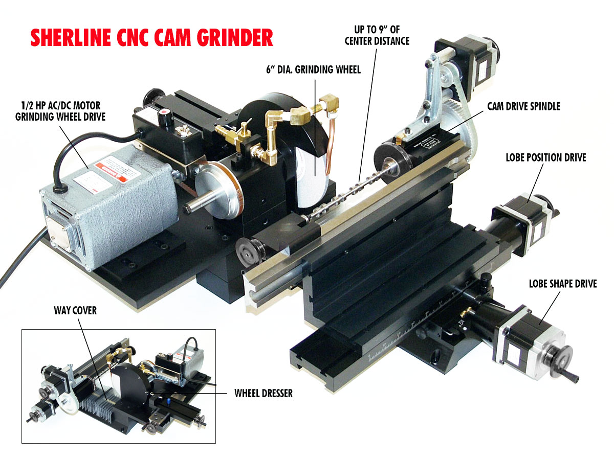
12. Grinding a cam for a model V4 engine by Joe Martin
Components of Joe’s CNC cam grinder. Click on photo to view a larger image.
Joe Martin put together a cam grinder from mostly off-the-shelf Sherline components, a coolant pump, and a few custom plumbing and bent brass pieces. He spent over three years developing the g-code software, which he wrote himself. The heart of the system is a 4″ grinding wheel driven by a Sherline headstock and a Sherline CNC rotary table to rotate the cam blank. Both are placed on a Sherline CNC mill base for in/out movement. An 18-minute video on how it works has been placed on YouTube. It had to be divided into two parts to fit within YouTube’s new 10-minute limit on video length. You can view the two halves of the video by clicking on the links below:
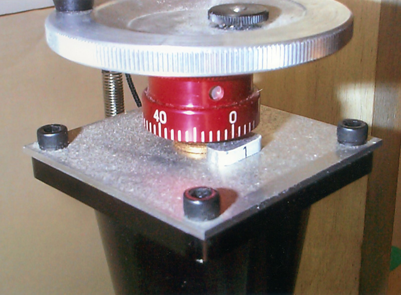
13. A lathe or mill power feed using an electric drill by Joe Katona
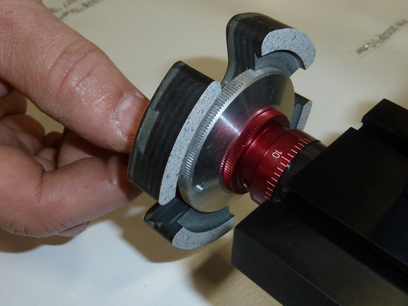
At the 2011 NAMES show in Detroit, Sherline dealer Joe Katona of JK Woodcraft came by the booth to show us a device he came up with to allow the use of a battery-powered drill or electric screwdriver to turn the handwheel to move the long axis of the lathe when moving over long travels. At 20 revolutions per inch, it can take a long time to manually move it through the 17″ center to center distance on the long-bed lathe. This adapter fits in a drill chuck and can either be left on the drill or left on the handwheel. It will work on the mill adjustable zero handwheels as well.
Figure 1—The adapter is shown pressed into position on a 4400 lathe crosslide handwheel. It really comes in handy on the longer axis but will work on any Sherline lathe or mill adjustable zero handwheel. Click on photo to view larger image.
Joe made the part on a Sherline CNC mill from ½” thick laminated phenolic plastic, a machineable thermoset material that will not mar the aluminum handwheels. This version was a press fit, but the cutouts allow you to use a rubber band to help hold it on if you prefer to leave it in place. Joe machined two “steps” inside to allow it to be used on 2″ or 2.5″ adjustable zero handwheels on his 4400 lathe. The cutout for the handwheel allows it to be used manually, even with the adapter in place. (A smaller version would be needed for use on plain 1-5/8″ handwheels.) The hardened hex stock was cut from an old hex wrench using an inserted tip ceramic cutter and simply pressed into a round hole. The ends were beveled slightly to remove sharp corners.
Figure 2—Here, you can see the two steps on the back side. Click on photo to view larger image.
The part was cut using a 1-1/4″ milling cutter, and 0,0 was the center of the part. He started with a 4″ square piece of stock. (CLICK HERE to copy the g-code text file he wrote.)
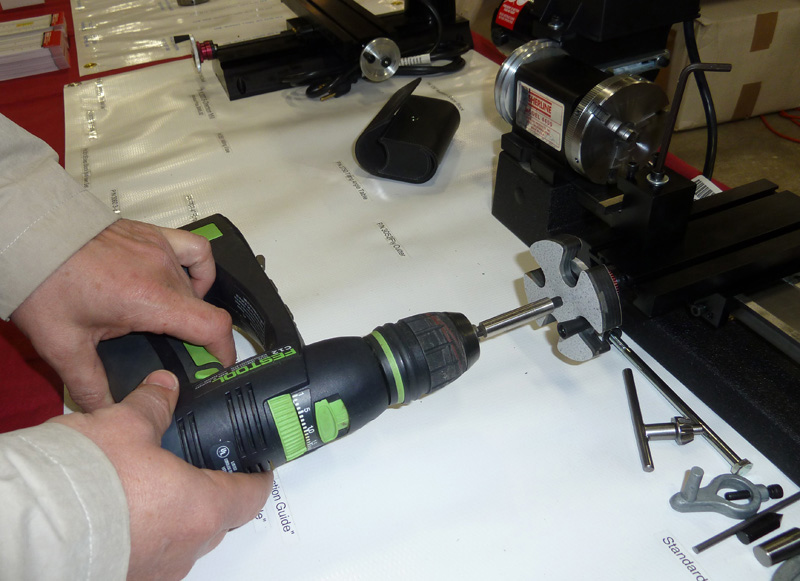
Figure 3—A reversible, battery-powered electric drill makes quick work of long travels in either direction. An electric screwdriver would work too. Click on photo to view larger image.

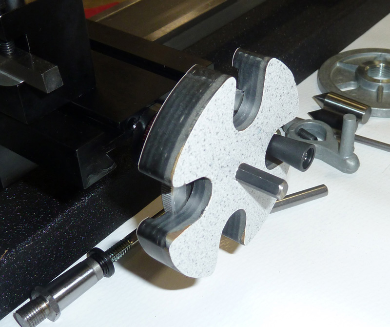
14. Making your own set of CNC Box wrenches by Joe Peitz
Joe Peitz of Nashua, NH, submitted a program and some photos showing how you can make your own set of box wrenches using a Sherline CNC mill. A couple of sub-routines are utilized. This project is a good example of the versatility of CNC. Here’s what he had to say:
“I ran into a Sherline 2000 at my local hobbyist club. I looked around and looked around for sample programs used for making box wrenches and couldn’t find one, so I wrote one and would like to pass it on for inclusion in your next software release if you think it passes muster. The program mills a box wrench out of sheet of material using only g-codes. By editing the program, you can change the number of flats, width, length, diameter, and depth of total cut, which are variables inside the program which is fairly heavily commented. It can result in a quite useable tool, and (I think) it shows off the power of G-code and the Sherline 2000. If you want to use it, feel free to edit it in any way and/or distribute it free from any copyrights.”
Shown above are several test parts cut from wood to test the g-code plus a piece of aluminum from which one of the wrenches was cut.
CLICK HERE to view a PDF file that further explains the process.
CLICK HERE to download a text file in .TXT format that contains the g-code. The code has a lot of comments added in parenthesis to explain the process in further detail. If you g-code experts out there have any suggestions for improvement we will pass them on to the author.