Below are a few problems and solutions relating to problems that have been noted in EMC and EMC2 as used by Sherline’s cnc machines. Before calling Sherline, please look over this list to see if an answer to your problem has already been posted. If you do call, please have your version number and/or approximate date of purchase ready.
CAUTION: When opening up your computer or driver box, please take appropriate grounding precautions to assure that static electricity does not damage delicate components on your circuit boards.
Finding which version of Linux you are running
In order to apply the appropriate remedy, it is usually necessary to know which version of Linux your machine is operating under. Before calling technical support, please have this information at hand. Here is how you find out:
Ubuntu version (EMC2): In the top menu bar of the desktop click on “System.” In the dropdown menu, click on “About Ubuntu.” In this box it will list the current version number.
Debian version (EMC): When booting up the computer, after the biostar logo appears on the screen a version page will show briefly. Hit the up or down cursor arrow on the keyboard to freeze the screen so you can copy down the version number.
Also, look at the backup CD’s that came with your computer or driver box. The Instructions/Utilities disk and Installation disk should have Sherline’s version numbers noted on them.
The computer runs a program and the stepper motor power is on, but none of the motors move
This is the most common call we get. Most likely you have not connected the 25-pin parallel cable to the computer. This cable, which sometimes used to be referred to as a “printer cable” comes from the driver box in the bottom of the computer case, and the other end must be connected to the computer’s parallel port. This is how the computer communicates with the driver board and stepper motors.
The stepper motors all stopped running at the same time and now won’t move
Starting with driver boards made in 2009, an additional level of protection was built into the board as a running change to automatically shut off power to the motors if an electrical anomaly that could damage the board is detected. Take a look at your setup to determine that nothing is physically jammed and then turn off power to the board using the power switch on the side of your computer or back of your driver box. Wait a few seconds and turn it back on. If the motors now work, it was the protection circuit doing its job. If this happens several times, you might want to take a look at your surge protector, other sources of electrical interference or physical obstructions that might be causing the protection circuit to activate. Before restarting, it is advisable to check that all cable plugs are fully engaged and dry (no liquid coolant contamination), and check each axis for free movement (lubrication and gib settings) to be sure those weren’t a source for the problem. If rebooting the driver power supply does not fix the problem, you may have a burned board and will need to call for technical assistance, but always try resetting the power supply before calling Sherline. Back to Top
…or, for computers and driver boxes shipped after mid-October, 2011—Fuse Replacement
In mid-October, 2011 replaceable fuses were added to the driver circuit board for additional protection. A blown fuse on one or more axes can be due to any of several different reasons; such as, motors plugged in or unplugged while the power is on (“hot plugging”), stalling or over-driving a motor by taking too heavy a cut, etc.
First try restarting the driver box as noted above. If this does not solve the problem, to change the fuse or fuses on a computer-mounted driver board, first turn off the computer and driver board power supply and unplug the power cord. Remove the side panel of the computer (the one with the machine on/off switch). Inside the PC you will see the circuit board attached to the top of its own power supply on the bottom of the computer case. There are four small vertical green fuses inline behind the DINN cable receptacles for each axis. You will find two replacement fuses taped inside the aluminum housing below the CD/DVD drive. Remove the fuse(s) from the non-functioning axis (axes) and replace the existing fuse(s) with a new one. Once the fuses are replaced, re-install the cover and turn power back on. If you are using an external 8760 controller you will find the fuses taped to the inside of the lid. Follow the same replacement procedure described above. Back to Top
The stepper motors make noise, but nothing is moving
The likely problem here is your mill is binding or not properly lubricated. With the more significant stress of quick back and forth motions and the high number of turns possible in a short period of time your mill will need to be more frequently lubricated than hand driven applications. Under continuous cnc use we recommend that Sherline cnc lathes and mills be lubricated once every four hours. Refer to the mill manual or https://sherline.com/lubricat.htm for more detailed lubrication instructions. Note also that when stepper motors are powered up but not yet running they do tend to make a slight buzzing or hissing noise. This is normal. Back to Top
The computer is plugged in and all cables are connected properly but the computer will not boot up
Unplug the computer and plug a test plug or a different electrical device into the same outlet to confirm that you do have power. (On some wall outlets the lower outlet is controlled by a wall switch that may be in the off position or a home circuit breaker may have blown.) If it still will not power up, the power supply may be damaged. Call Sherline to obtain an RMA number to replace your PC power supply. If not under warranty you may do the repair yourself by purchasing a standard PC power supply (≥400W) and soldering 3 wires to the AC inlet for PCBA power supply. Back to Top
One or more axes are going in the wrong direction in Jog mode
NOTE: By convention in the world of cnc, correct directions of TABLE movement based on the Cartesian co-ordinate system are as follows:
X-axis, + = table moves to left (tool appears to move to right)
Y-axis, + = saddle moves toward operator (tool appears to move away from operator)
Z-axis, + = spindle moves upward
A-axis, + = clockwise rotation of table
Programming is done on the basis of APPARENT TOOL MOVEMENT which is the opposite of XY table movement, so some new users assume the X and Y axes are moving in the wrong directions. Before making any changes be sure the direction actually IS wrong.
If an axis really is moving in the wrong direction this means that your .ini file has been changed from the factory settings at some point. To correct it you will need to open the .ini file for your particular inch or metric mill or lathe. To get to these files from the Ubuntu desktop screen go to the main menu bar at the top of the screen and click on Places Tab. In the dropdown menu, select the Home folder, then click the emc2 folder, then configs, then double click on the appropriate .ini file for your lathe or mill. In the box that appears, choose “Display.” This will open the .ini file. In EMC2 the files are named as follows:
Inch mill = Sherline4axis_inch.ini
Metric mill = Sherline4axis_mm.ini
Inch lathe = SherlineLathe_inch.ini
Metric lathe = SherlineLathe_mm.ini
CAUTION: Values in the .ini files control all the functions of the EMC2. Do not change these values unless you are an experienced Linux and EMC2 user or are carefully following these instructions.
The various axes are numbered in the EMC2 rather than lettered. For the mill, axis 0 is the X axis, Axis 1 is the Y axis, Axis 2 is the Z axis and Axis 3 refers to the A (rotary) axis. Scroll down through the information presented to the section entitled “#Axis sections.” Find the axis you wish to change (1, 2, 3 or 4) and look for the scale factor line titled “SCALE.” There will be a number after it. If there is no symbol in front of the number it is positive. If there is a minus symbol in front of it, it is negative. To change the direction of movement for that axis, simply add or delete the minus sign. To exit the file, click on the box with the X in it in the upper right-hand corner of the screen. In the window that opens, Click “Save.”
When you’re finished making changes, restart the EMC2 program for your machine. A reboot should not be necessary, but is a good practice to make sure the changes take effect. Should you ever need original copies of the .ini files, replacements (and their instructions) can be downloaded at the EMC section of the Sherline website at INI File Replacements. We recommend copying the existing ini files and saving them under a different name before attempting modifications. If your changes do not work, you can always go back to your original configuration by replacing the updated files with your copy of the original.
Here are the factory settings for SCALE for the various axes in each .ini file:
| Axis | Mill, inch | Mill, mm | Lathe, inch | Lathe, mm |
| 0 (X) | 16000 | 800 | -16000 | -800 |
| 1 (Y) | -16000 | -800 | -16000 | -800 |
| 2 (Z) | -16000 | -800 | -16000 | -800 |
| 3 (A) | 160 | 160 |
What if one of my CNC axes stops moving?
It is likely that a fuse in the driver box has blown to protect the circuit. Spare fuses are wrapped in plastic and taped inside the cover lid. For more details on accessing the circuit board and replacing the fuses click on the following link to the instructions for P/N 8760 CNC 4-axis Driver Box.
An error message that reads “Radius to end of arc differs from radius to start”
This means the endpoint of the previous line does not match the coordinates specified and required by the radius command. The tolerance for the precision of these two points can be adjusted in the INI files of version 4.51 or higher. Back to Top
Making Tolerance Changes to EMC
Computers can be maddening devices because they demand accuracy beyond what normal human beings find useful. This can be especially true when producing cnc programs, and where this condition shows up the most is when you are working with radius ending points.
In order to cut a curve, the g02, g03, and r commands must be used. When you use these commands, you must tell your computer the exact ending position of the curve. The computer will give you a message stating that your end x/y position is in error, but it will not fix it for you. The computer is demanding an accuracy far greater than the user believes the part needs and who may have carelessly made a few rounding errors.
Because Sherline cnc customers have been having problems with this, we decided in 11/06 to open up this tolerance up to a maximum error of 0.001″ (0.002 mm) standard.
If you are still constantly having this kind of problem, you can either increase the accuracy of your drawing or force the computer to accept your faulty math by opening up the tolerance in the .ini files, although Sherline doesn’t recommend it, believing two wrongs don’t equal one right. The radius point tolerance can be altered in EMC v4.51 and higher in the .ini files. Altering the .ini files of previous versions will not fix the problem; however, the EMC can be upgraded online without the need for reinstallation of the software. Sherline Linux computers of version 4.xx and higher are configured for connection to the Internet. Once connected to the Internet with the proper network cable, open a terminal (Main Menu: Applications>Accessories>Terminal) and type:
sudo apt-get update
Hit [Enter] key to start download, then type:
sudo apt-get install emc emc-modules-2.6.16-rtai
Hit [Enter] to install download
To change the tolerance for radius and tangent points, simply edit the numerical values in the .ini files (mill_inch_freq.ini and mill_mm_freq.ini). The lines should be by default:
INCH_TOLERANCE = 0.0005 or 0.0010 (SP setting)
MM_TOLERANCE = 0.001 or 0.002 (SP setting) Back to Top
Changing the Axis Scale
Changing the axis scale (for non-Sherline leadscrews with a thread count other than 20 TPI or 1 mm for example) can be achieved by editing the input and output scale values in the EMC .ini files (mill_inch_mini.ini or mill_mm_mini.ini) for the Standard and Metric versions of the EMC2, respectively). To open these files, go to Places>HomeFolder>emc2>configs>Sherline then double click the appropriate file; i.e., mill_inch_mini.ini or mill_mm_mini.ini and so on. When the prompt appears, select “Display File.”
About a quarter of the way into the file you will see the section labeled “; Axes sections ————-” where the settings for all four axes are located. For each axis you wish to change the scale on, go down to the lines that read “INPUT_SCALE =” and “OUTPUT SCALE =”. These values are normally 16000 (or -16000) in the Inch .ini file and 800 (or -800) in the Metric .ini file. Changing these values will affect how far the axes travel for every unit jogged. For example, dividing the values by 10 would cause an axis to move .1″ when jogged by 1″. So, when a machine is switched from a standard 20-TPI leadscrew to a 4-TPI leadscrew, for instance, changing the scale values from 16000 to 3200 would compensate for this and return the machine to a normal movement scale. When changing these values, make sure to leave the number either positive or negative, as changing this will reverse the direction the axis moves unless this is what you want to do.
There are a number of other values in the .ini files that can be altered to change the way the EMC functions, although experimenting with these may have effects ranging from the EMC functioning properly to your program becoming impaired or inoperable. When you’re finished making whatever changes you like, simply save the file and restart the EMC if it’s currently open. A reboot should not be necessary but is a good practice to make sure the changes take effect. Should you ever need original copies of the .ini files, replacements (and their instructions) can be downloaded at the EMC section of the Sherline website at INI File Replacements. We recommend copying the existing .ini files and saving the copy in a safe place before attempting modifications. If your changes do not work, you can always get back to your original configuration by replacing the updated files with your copy of the original. Back to Top
One or more stepper motors skip steps during rapid travel at full speed
A fact when dealing with stepper motors is that the faster they turn, the less torque they have. This is because the power for each pulse is on for shorter periods of time; therefore, it’s a good idea to keep feed rates 20% below maximum when running programs with many short moves, particularly on the Z-axis. The maximum feed rate in EMC2 is 22 in/min. Therefore it is good practice to keep your feed rate below about 18 in/min or 450 mm/min. Some of our customers have counterbalanced the weight of the Z-axis with a simple rope-pulley-weight device to reduce wear on the Z-axis leadscrew. See the CNC Project section of our website for a photo and description of how one person did this. You’ll find that the stepper motor system we use quite reliable and capable of running complex programs without losing steps when used properly.
G-code tips: Start and end each program with a percentage sign. Put a g40, g49, g21 (Metric) or g20 (inch) and g90 in the first line of code to cancel out any previous codes that might be left over from the last program, and always end the program by returning to the same place you started. Keep in mind which g-codes EMC2 does and does not support. Some canned cycles are not supported, for example. Back to Top
The computer locks up after running a small program a number of times (early versions)
This should not occur in the Ubuntu versions of EMC2, but if you have a version of EMC earlier than 4.37 the problem may be due to a buildup of CPU usage caused by running the same program over and over. (CPU usage is shown in a small window near the bottom right of your screen.) Rebooting each time will work but is time-consuming. Your best solution is to turn off the Backplot program when running short programs repeatedly. Another workaround is to copy and paste a number of copies of the small program into one longer program. Put an M0 command between each copy of the program to pause the machine. When you replace your part, just hit the [Resume] button to continue. Back to Top
Editing the Tools Table—Default numbers must be deleted and replaced with real tool info before proceeding
If you are using the LinuxCNC and using the Sherline Base Page that comes with our disc, then the tooling page is different than the LinuxCNC tooling page. On the Sherline Base Page, when you first install it and click on the Tooling page you will see what I show below. All of the tooling information that is shown on the original page is Sample Info and it doesn’t work.
Very Important: If you just edit the Sample info that is already on the tooling page and put in the tool info for the tools that you are using, it will not work! You need to get rid of all of the sample information and start fresh.
Default Tooling Page when first installed:
| Tool # | Length | Dia. | Comment |
| T2 | D0.06250 | Z+0.100000 | {;1/16} endmill |
| T3 | D0.20100 | Z+1.27300 | {??????} |
| T99999 | Z+0.100000 | ;BIG | |
| ADD EXTRA TOOL | REMOVE LAST TOOL |
In order to input any information into the tooling page that will work, you need to remove all of the default tooling information.
To do this you click on “REMOVE LAST TOOL” three times. This will get rid of the tooling info for the three tools shown above.
Then you click on “ADD EXTRA TOOL”, and input your real tool information.
Your new tooling page information should look something like this:
| Tool # | Length | Dia. | Comment |
| #1 | -.2 | .1875 | 3/16² Spot Drill |
| #2 | -1.0 | .125 | 1/8² Drill |
I don’t know where they came up with the default information, but it is for show only. It is a poor example of what should be on the tooling page, and it doesn’t work. Again, you need to remove all of it and start fresh. Back to Top
Suggestion for tool holders and setting up your tools
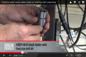
If you check out this video you will see a Drill Chuck Holder #3074 and other end mill holders in use.
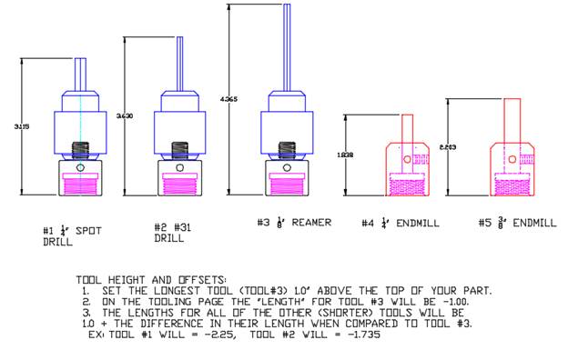
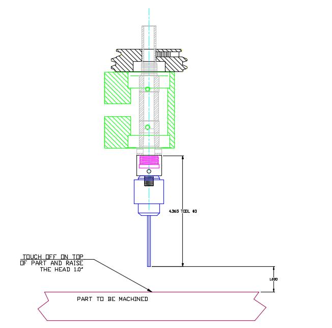
If you use the #3074 for all of your drills and the endmill holders for your other cutters, setting up your tools and your tool offsets is very easy. The endmill style holders all locate against the shoulder of the headstock spindle. If you use a separate holder for each of your tools, you can measure the overall length of the tool and the holder for each tool. You set up your Z Home position by putting the longest tool on the spindle (in the diagram below it is tool #3). Then you lower the tool until the tip of the tool touches the top of the part (use a piece of .001 shim stock as a feeler gage for tip contact with the top of the part). Then you raise the head 1.0” (or whatever amount of clearance you want between the tip of the tool and the top of the part). This Z level is now your Z home position that all of your tool offset lengths will be set from.
If you use this method, setting up your jobs will be easier.
—Karl Rohlin
Upgrading your older computer to the latest version of Linux and EMC2
Depending on how old your computer is, you may or may not be able to upgrade to the latest version. As each version has been introduced, it has become more sophisticated and requires more system resources to run properly. Over the years we have constantly upgraded our motherboards and memory to keep up with these increasing demands. Any current PC has plenty of speed and memory for running Linux and EMC2; however, finding a new computer with a parallel port is very difficult, as most computers now rely only on USB connections. At this time, USB still does not have the capacity to push enough data through a serial port to run up to four axes reliably at the same time. (Sherline does offer a new computer with a parallel port, built in 4-axis driver board and separate power supply as P/N 87610.) Our current requirements are for at least 512 MB of RAM, at least 800 MHz clock speed and a 25-pin parallel port. Some of the earliest motherboards used by Sherline came with 128 MB of RAM and may not support more than 256 MB in an upgrade. Current versions also come with a CD drive and a USB port and flash drive in place of the original floppy drive.
The version of Linux and EMC2 that we supply has been specially configured to match the capabilities of Sherline machines and is not identical to versions that you might download from the Internet from other sources. A copy of the current Sherline version of Linux and EMC2 is available on CD as P/N 8326. It comes with a 2nd CD with the current instructions and free utilities.
Sherline computers only a few years old can probably be upgraded, but some of the very early motherboards may not. Call Sherline with the version number of your software and we will help you assess your upgrade options. (See beginning of this page for how to find version numbers.) Back to Top
EMC Related Documents
EMC User Handbook (PDF)
EMC Developer Handbook (PDF)
EMC Integrator Handbook (PDF)
EMC Glossary (PDF)