Links to Sherline Accessory Instructions
One of the things that set Sherline apart from other machine tools is the complete instructions we have prepared for all our machines and accessories. A full-color Instruction Guide comes with each machine. In addition, each accessory comes with its own complete instructions, if needed. If you are not sure how to locate the name of the accessory you are looking for, use our a cross-referenced list, Sherline Part-Number Finder.
Assembly and Instruction Guide
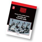 CLICK HERE to view the instruction manual that comes with each Sherline lathe or vertical milling machine as a PDF file. Included are exploded view parts drawings of each machine.
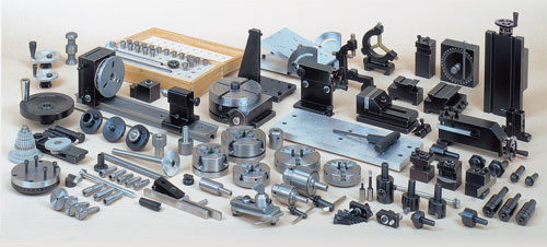
Following is a list of the lathe and mill accessories. Click on any accessory part number below to see instructions for that part. The instructions are in .pdf format.
Sherline also offers a printed book called the Sherline Shop Accessories Guide (P/N 5327), which is a collection of all the instructions and help sheets we have produced. If you prefer to buy them all at once, you can order the book by clicking on the link above. If you just want to read about a particular accessory or would prefer to print out all the instructions yourself, the following list is your gateway to many excellent free machining instructions. It can be applied not only to Sherline machines, but most of the knowledge is equally applicable to machines of any size or brand.
Help Sheets
Several instructions are available on procedures for your Sherline lathe and vertical milling machine. Learn about installing new gibs, changing a machine from inch to metric or vice versa, installing stepper motor mounts, and adding a reversing switch to your speed control…it’s all there for you to read or print out. See the “Help Sheets” page.
- Tool Post Options — A summary of standard and optional tool posts available
- 1010 — 5/32″ headstock chuck & key or P/N 1015 5/32″ tailstock chuck & key
- 1016 — 5/32″ Drill Chuck with adjustable tailstock holder & key
- 1030/1044 — 1030 3.125″ dia. and 1044, 1071 and 1073 2.5″ dia. 4-jaw chucks
- 1040/1041 — 1040 3.125″ dia. and P/N 1041 2.5″ dia. 3-jaw, self-centering chucks
- 1065 — 5/8″ shank to 3/4-16 Chuck Adapter (descriptive page)
- 1066 — 1/2″ shank to 3/4-16 Chuck Adapter (descriptive page)
- 1069 — 3/8″ or P/N 1072 1/4″ tailstock chuck & key
- 1072, 3072, 1069, 3073, 1010,1015 — All Jacobs Drill Chucks
- 1074 — Steady rest
- 1075/1076 — 2.5″ and 3.1″ 4-jaw, self-centering chuck
- 1076C-PIE — Pie jaws for 4-jaw, self-centering chuck
- 1080 — Older style compound slide (replaced by P/N 1270 – as of 4/1/98)
- 1090 — Follower rest
- 1140 — Pin Jaws for 1040 3-jaw chuck
- 1141-1149 — Interchangeable Top Jaws for Sherline Scrolling Chucks
- 1150 — Lever Collet Closer
- 1152-1153 — Lever collet closer accessories (1152 LCC riser, 1153 Collet stop kit)
- 1156 — #1 Morse Taper Removal Tool
- 1160 — WW collet set and 1162 deluxe boxed collet set
- 1182 — Bullnose live center
- 1182PC — Pool cue live center
- 1185 — Vertical milling table
- 1191 — Live center
- 11975 — Vertical Sheer Bit
- 1201 — Adjustable live center
- 1202 — Adjustable tailstock 1/4″ or 3/8″ Jacobs chuck holder
- 1203 — Adjustable tailstock custom tool holder
- 1204 — Adjustable tailstock 0JT 5/32″ Jacobs chuck holder
- 1206 — Adjustable tailstock 1″ threading die holder w/ 13/16″ bushing
- 1220 — Tailstock spindle extender (for lathes made prior to July 1996)
- 1230 — #0 Morse to 3/4-16 chuck adapter (descriptive page)
- 1270 — Compound slide (replaces P/N 1080 – as of 4/1/98)
- 1286 — Rear-Mount Riser Cutoff Holder
- 1290 — Steady rest riser block
- 1291 — Lathe riser block and riser tool post
- 1292 — Tailstock riser block
- 1294-1295 — Riser plate for 8″ and 13″ crosslide
- 1297 — Headstock riser block
- 1299 — Double Headstock riser block
- 2049 — Spindle handwheel
- 2085/2086 — WW collet tailstock adaptor
- 2090-2096 — Clockmaker’s arbors
- 2100 and 2101 — Collet pot chucks-3/4″ and 1″
- 2110 — W.R. Smith T-rest and “Making Gravers” (article by William R. Smith)
- 2125/2126 — Microscope and/or Mount for lathe (DISCONTINUED 5/13) Instructions remain for reference HERE.
- 2200 — Radius-cutting attachment
- 2250 — Quick-change tool post and holders
- 2256, 2257, 2258 — 3/8″ LH and RH inserted tip tool holders
- 2259, 2260, 2261 — 80° and 55° inserted tip boring tool holders
- 2265 — Ceramic Insert Tool Holder
- 2275 — Bump Knurl Tool Holder
- 2295 — Quick-change carbide insert tool holder (Same links as 2250 above)
- 3001 — 110 VAC power feed (DISCONTINUED 5/21) Instructions remain for reference HERE.
- 3002 — Cut-off tool & holder
- 3003 — Two-position tool post, 1/4″-1/4″ (descriptive page)
- 3004 — Knurling tool holder
- 3005, 3006 (Carbide), 3007 — Cutting tools
- 3008 — Two-position tool post, 5/16″-3/8″ (descriptive page)
- 3009 — Lathe tool height gauge
- 30113 — 3C Collet Headstock
- 3015 — Switch dust cover
- 3016 — Cut-off tool rear mounting block
- 3017 — Crosslide accessory plate
- 3018 — Rear mount cut-off tool holder
- 3020 — Sherline “T” driver (descriptive page)
- 3021 — Center drill set (descriptive page)
- 3035 — Spur driver (descriptive page)
- 3038 — Wood tool rest (also 3047 Extended tool rest) (DISCONTINUED 2022) Instructions remain for reference only HERE.
- “Grinding Your Own Lathe Tools”
- 3050/3053 — Vertical milling column – converts lathe into a mill in one minute! (also P/N 3480/3485 with adjustable “zero” handwheel)
- 3057 — Rocker tool post (descriptive page)
- 3059 — Slow-Speed Attachment (DISCONTINUED 2001) Instructions remain for reference only HERE.
- 3100 — Thread-cutting attachment
- 3400 — Oversize handwheel
- 3420/3470 — Adjustable “zero” handwheels
- 3580 — 8-direction vertical milling column
- 40040 — Drive belt
- 4007 — Faceplate and P/N 4009 drive dog
- 40116 — Lathe Headstock Hard Stop kit
- 4098/4099 — Gib Replacement (Lathe crosslide, Mill X- and Y-axis)/(Lathe saddle, Mill Z-axis)
- 40992 — Gib Removal Tool
- 4150/4151 — 15″ or 24″ lathe dust covers
- 4335 — 10,000 RPM Pulley Set
- 4360 — Chip guard
- 4412A — Morse #1 taper tailstock for pen makers
- 4417Z/4417ZM — CNC Leadscrew backlash adjustment upgrade
- 5300 — The Home Shop Machinist’s Handbook by Doug Briny
- 5301 — Tabletop Machining by Joe Martin
- 5335 — Sherline Lathe Basics Video on DVD by Mike Rehmus
- 5930/5935 — Four position gang-tooling tool posts (5930 3/8″, 5935 5/8″)
- 5931/5936 — Rear side cutoff multi-tool holders (5931 3/8″, 5936 5/8″)
- 5932/5937 — Front side multi-tool holders (5932 3/8″, 5937 5/8″)
- 5941/5942 — Rear Side Multi-Tool Holders (5941 3/8″, 5942 5/8″)
- 65027 — ER-16 Collet Nut Spanner Set
- 67126 — Installing Sherline High-Torque Stepper Motors on Leadscrew Machines
- 67126— Installing Sherline High-Torque Stepper Motors on Ball Screw Machines
- 67127 — Installing Sherline Stepper Motors
- 6720 — Adding stepper motor mounts to your lathe
- 7600 — 3/8″ Insert holder tool posts and Valenite carbide cutting tool holders and insert tips
- Using carbide tipped tools
- 7610 — 55° negative rake insert holder OBSOLETE 6/14, No longer available
- 8200/8260 — Lathe digital readout
- 88200-CNC — Installing DRO handwheels onto the back of Sherline stepper motors
- 8760 — CNC 4-axis driver box
- 8763 — Parallel port signal amplifier
- 8815 — Installing the pneumatic cylinder and components for the pneumatic bar feeder
- 8825 — Pneumatic bar feeder assembly instructions
- 1012 — Sensitive drilling attachment
- 1156 — #1 Morse Taper Removal Tool
- 1164 — WW collet fixture (or P/N 1165 8 mm collet fixture)(for rotary table or mill table.)
- 1187 — Chuck-to-T-slot adapter
- 1297 — Mill headstock spacer block
- 2045 — Index block set
- 2118 — Horological Milling Machine Bushing and Depthing Accessory
- 2127/2128 — Microscope and/or mount for Sherline mills (DISCONTINUED 5/13) Instructions remain for reference only HERE.
- 3012 — Hold-down set
- 3013 — Step block hold-down set
- 3014 — ¼” Step block hold-down set
- 3049 — Boring head, metric (Inch, see P/N 3054)
- 3052 — Fly cutter (includes 3065)
- 3054 — Boring head, inch (Metric, see P/N 3049)
- 3055 — Morse #1 blank
- 3058 — 4-jaw chuck hold-down set
- 3060 — Milling collets
- 3065 — Slitting saw holder (pdf version—includes 3052)
- 3061/3063 — Boring tools
- 3072 — Drill chuck and drawbolt
- 3079/6079/6080 — End mill holders
- 3200 — Indexing attachment
- 3230 — Mill cutter arbors (Also 3231, 3235 and 3236)
- 3500 — Rotary column attachment
- 3551 — Milling vise
- 3552 — Sherline MB Vise Fixture
- 3559 — 90° Angle plate
- 3560 — Mill tooling plate (4″ x 10″)
- 3562 — Mill tooling plate (7″ X 13″)
- 3570 — Mill vise rotating base
- 3700 — 4″ Rotary table
- 3701 — Right angle attachment
- 3702 — Right angle tailstock
- 3750 — Tilting angle table
- 4017 — Saddle nut replacement
- 4017U — Mill saddle lock upgrade
- 4017Z — CNC Mill Z-axis backlash lock
- 4335 — 10,000 RPM Pulley Set
- 5011U/5111U — Mill X- and Y-axis Backlash Lock Upgrade
- 5090 — Mill Accordion Way Covers
- 50911 — Sherline Mill Saddle with Oiler
- 5150 — Vertical mill vinyl dust covers
- 5200 — XY base
- 5201 — XYZ base
- 5328 — Steam engine video (Instructional)
- 54182 — 18″ Mill table installation
- 5650 — Mill conversion, 5000-series mill to 8-way column
- 6100 — Horizontal milling conversion
- 6101 — Mill column modification for use with horizontal milling conversion
- 6700 — Adding stepper motor mounts to your mill
- 67126 — Installing Sherline High-Torque Stepper Motors
- 67127 — Installing Sherline Stepper Motors
- 7620 — Carbide inserted tip fly cutter
- 8100/8160 — Mill digital readout
- 8700 — CNC rotary table
- 8710 — CNC rotary table riser plate
- 8760 — CNC 4-axis driver box
- 8763 — Parallel port signal amplifier
- 8800 — CNC Linear Controller (Inch)
- 8810 — CNC Linear Controller (Metric)
- 8850 — CNC Mill power feed (Inch)
- 8851 — CNC Mill power feed (Metric)
- 8900 — High-speed air spindle and headstock for engraving
- 8955 — Laser Mount for milling machines
- DC Motor Wiring
- Changing DC Motor Brushes
- DC Motor Assembly and Operation
Kit Instructions
- J1000 — “Jack-in-a-Box” machinist’s puzzle kit for the mill, Includes raw materials plus required tools
- T1000 — “Turner’s Cube” machinist’s puzzle kit for the lathe, Includes raw materials plus required tools (except 4-jaw, self-centering chuck)
- T1076 — Same as above but includes P/N 1076 4-jaw, self-centering chuck in kit
- “Millie” Steam Engine — Kit includes materials and instructions