|
|
Always wear safety glasses when operating machine tools. |
|
Download PDF Assembly and Instruction Guide
|
Download PDF 12″ Mill Base Dimensions
|
|
Download PDF 5000/5400 Mill Column Base Dimensions
|
Download PDF Mill Saddle Lubrication instructions
|
Back to MILLING MACHINE

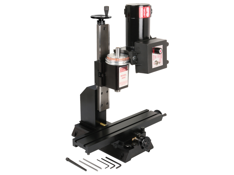
12" Manual Mill

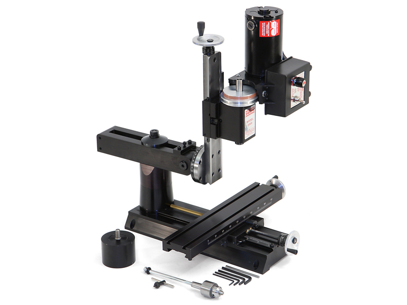
12" Manual Mill with optional accessory package
Image shown is a representation only. Actual product may vary.
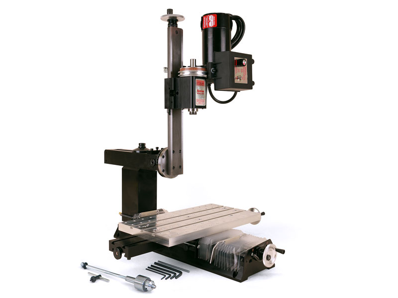
12″ Deluxe Mill
The 12″ Deluxe Tabletop Mill is Sherline’s most popular milling machine, offering an ideal balance of precision, versatility, and value.
Like all Sherline milling machines, the 12″ mill is built in the USA and features:
- Precision-machined dovetailed slides with adjustable gibs
- Permanently lubricated spindle bearings
- Adjustable preload, anti-backlash leadscrews
- A high-torque 90V DC motor with electronic speed control
Spindle speed is continuously variable from 70 to 2800 RPM—no belt or gear changes required. A secondary pulley position provides additional torque for low-speed operations.
This compact tabletop mill is ideal for customers who need a high-precision mini milling machine for small parts. Despite its small footprint, it’s capable of machining wood, plastic, aluminum, and even steel with exceptional accuracy. The 10″ benchtop mill delivers full-size performance in a desktop-sized package—making it perfect for home shops, labs, and prototyping environments.
Note on Ordering a Metric Mill – Most Sherline cutting tool, such as center drills, are offered in fractional sizes. If you opt for a metric machine with metric collets or holders, you’ll need to order compatible fractional-size holders to use these tools effectively.
Standard Equipment for the 12″ Benchtop Mill
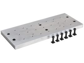
- 12″ base with laser-engraved scales
- Brass leadscrew cover that keeps chips off the rear of the Y-axis leadscrew
- 2.75″ (70 mm) x 13.0″ (330 mm) table with laser-engraved scales and two T-slots
- 1.235″ headstock spacer block
- Resettable, zero-adjustable handwheels:
- (2) 2″ (51 mm) handwheels on X- and Y-axes
- (1) 2-1/2″ (63 mm) handwheel on Z-axis
- All with laser-engraved aluminum collars
- ¼” Drill Chuck w/ key, #1 Morse arbor with drawbolt
- Pulleys, drive belt, three hexagonal keys, spindle bars, gib removal tool, eight-foot three-wire power cord, and instruction manual
- Oil reservoirs on the X/Y axes and the Z axis help keep critical parts lubricated. These were initially developed for CNC machines that run constantly for hours on end but can benefit manual machines as well
-


| Max clearance (table to spindle) |
8.00″ (203 mm) |
|---|---|
| Throat (no spacer) |
Optional |
| Throat (w/ headstock spacer) |
Adjustable |
| Travel, “X” Axis | 8.65″ (220 mm) |
| Travel, “Y” Axis | 5.00″ (127 mm) |
| Travel, “Z” Axis | 6.25″ (159 mm) |
| Hole through spindle | .405″ (10 mm) |
| Spindle nose thread | 3/4″-16 T.P.I. |
| Spindle nose taper | #1 Morse |
| Spindle runout of Morse taper | .0005″ or less |
| Handwheel graduations | .001″ (.01 mm) |
| Electronically controlled spindle speed range | 70 to 2800 RPM |
| Width Overall* | 15.00″ (381 mm) |
| Depth Overall* | Base footprint: 13.875″ (352.5 mm); With fully extended brass leadscrew cover: 16.75″ (425.5 mm) |
| Height Overall (Max.)* | 20.75″ (527 mm) |
| Table size | 2.75″ x 13.00″ (70 x 330 mm) |
| Hold-down provision | 2 T-Slots |
| Shipping Weight | 40 lb. (18.2 kg) | Movements in addition to X-, Y- and Z-axes |
Headstock rotation (90° left/right) |
| Motor | 90 volt DC with electronic speed control that accepts any incoming current from 100VAC to 240 VAC, 50 Hz or 60 Hz. Click here for motor specifications |
| Spindle Speed Range | 70-2800 RPM continuously variable by electronic speed control |
*Overall dimensions include motor and speed control
Click on the link for the exploded view of the 5000 and 5400 Series Manual Mills to help identify replacement parts.
If you are still uncertain please call our customer service representatives for help with this item.
Click the P/Ns below to download a zipped version of the IGS 3D CAD file. You will need to extract the zip file before viewing the files.
5400 3D IGS model
You need an IGS viewer to open .igs files. CLICK HERE to download a FREE IGS viewer.
 |
|
 |
 |
|
|---|---|---|---|---|
| 5000 (5100) | 5400 (5410) | 2000 (2010) | 5800 (5810) | |
| Max. clearance (table to spindle) |
8.00″ (203 mm) | 8.00″ (203 mm) | 9.00″ (229 mm) | 14.00″ (356 mm) |
| Throat (no spacer) | 2.25″ (50 mm) | 2.25″ (50 mm) | Adjustable | Adjustable |
| Throat (w/ headstock spacer) | Optional | 3.50″ (90 mm) | Adjustable | Adjustable |
| Travel: X-axis (with stop) | 8.65″ (220 mm) | 8.65″ (220 mm) | 8.65″ (220 mm) | 13.65″ (347 mm) |
| Travel: Y-axis | 3.00″ (76 mm) | 5.00″ (127 mm) | 7.00″ (178 mm) | 11.00″ (279 mm) |
| Travel: Z-axis | 6.25″ (159 mm) | 6.25″ (159 mm) | 5.38″ (137 mm) | 9.38″ (238 mm) |
| Hole through spindle | .405″ (10 mm) | .405″ (10 mm) | .405″ (10 mm) | .405″ (10 mm) |
| Spindle nose thread | 3/4-16 T.P.I. | 3/4-16 T.P.I. | 3/4-16 T.P.I. | 3/4-16 T.P.I. |
| Spindle nose taper | #1 Morse | #1 Morse | #1 Morse | #1 Morse |
| Spindle runout of Morse taper | .0005″ or less | .0005″ or less | .0005″ or less | .0005″ or less |
| Handwheel graduations | .001″ (.01 mm) | .001″ (.01 mm) | .001″ (.01 mm) | .001″ (.01 mm) |
| Handwheel Type | Standard Handwheels | Zero Adjustable Handwheels (With the exception of DRO machines which come with DRO handwheels) | Zero Adjustable Handwheels (With the exception of DRO machines which come with DRO handwheels) | Zero Adjustable Handwheels (With the exception of DRO machines which come with DRO handwheels) |
| Electronically controlled spindle speed range |
70 to 2800 RPM | 70 to 2800 RPM | 70 to 2800 RPM | 70 to 2800 RPM |
| Width overall | 14.75″ (375 mm | 15.00″ (381 mm) | 15.00″ (381 mm) | 20.00 (508 mm) |
| Depth overall | 11.75″ (298 mm) | 14.00″ (356 mm) | 22.25″ (565 mm) | 23.13″ (588 mm) |
| Height overall (Max.) | 20.75″ (527 mm) | 20.75″ (527 mm) | 23.38″ (568 mm) | 24.50″ (622 mm) |
| Table size | 2.75″ x 13.00″ (70 mm x 330 mm) |
2.75″ x 13.00″ (70 mm x 330 mm) |
2.75″ x 13.00″ (70 mm x 330 mm) |
2.75″ x 18.00″ (70 x 457 mm) |
| Hold-down provision | 2 T-slots | 2 T-slots | 2 T-slots | 3 T-slots |
| Shipping weight | 33 lb (15.0 kg) | 36 lb (16.3 kg) | 38 lb (17.2 kg) | 50 lb. (22.7 kg) |
| Movements in addition to X-, Y- and Z-axes |
Headstock rotation (90° L/R) |
Headstock rotation (90° L/R) |
Headstock rotation (90° L/R) |
Headstock rotation (90° L/R) |
| Column rotation | N/A | N/A | (90° L/R) | N/A |
| Column pivot | N/A | N/A | (90° Fwd/Bk) | (90° Fwd/Bk) |
| Column swing | N/A | N/A | (90°L/R) | (90°L/R) |
| Column travel | N/A | N/A | (In/Out) 5.5″ (140 mm) | (In/Out) 5.5″ (140 mm) |
| Motor Specs | ||||
| Input voltage | 100 to 240 VAC, 50 or 60 Hz | |||
| Output to motor | 90 VDC | |||
| Current draw | .5 to 15 amps depending on load | |||
| No-load output shaft speed | 6000 RPM (no pulley) | |||
| Click here for more detailed specs | ||||
| Spindle Specs | ||||
| Spindle End play (factory adjustment of preload) |
.0002″ (.005 mm) or less, normal pulleys | |||
| Runout at nose | .0005″ (0.013 mm) or less | |||
| Bearings | Two 20 mm lifetime lubricated ball bearings with adjustable preload | |||
Related products
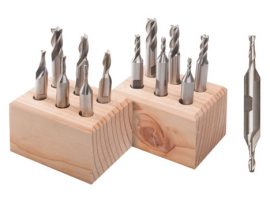
3/8″ Double-Ended End Mill Sets
These precision 3/8″ shank double-ended end mill sets are a versatile and budget-friendly choice for general milling work. Double-ended cutters give you two cutting ends in one tool, doubling your productivity and value. Each cutter features a flat section on the shank for secure clamping in a 3/8″ end mill holder.
Both sets include six popular diameters: 1/8″, 5/32″, 3/16″, 1/4″, 5/16″ and 3/8″.
7400 – 2-Flute Set
Ideal for softer materials such as aluminum, these 2-flute cutters resist clogging and provide smooth chip evacuation.
7401 – 4-Flute Set
With four cutting edges, this set offers increased cutting contact and is better suited for harder materials like steel.
Each set includes a wooden storage block to protect your cutters when not in use
CAUTION: Unlike a drill bit that looks similar, end mills are sharpened on the edges as well as the tip. These sharp edges demand a lot of respect when being handled and used! Also, to keep them sharp, store them in the block provided or individually protected in your toolbox.
Price range: $39.82 through $56.89
Select options
This product has multiple variants. The options may be chosen on the product page
