About the Headstock w/Flat Base
The Sherline industrial headstocks were developed based on the headstock used on the Sherline lathe and milling machine. The headstocks are made from extruded 6061-T6 aluminum and have a black anodized finish. They are available with your choice of a spindle (3/4-16 #1M taper or an ER-16*).
All Sherline Industrial spindles feature lifetime lubricated bearings with adjustable preload. The bearings are Class 5 for better accuracy, tighter tolerance, smoother and quieter movement, and cooler running. The bearings in all our industrial headstocks, except for the 3C headstock, are 6004-VV C3P5 – ABEC 5. The headstock bearings are rated for a continuous speed up to approximately 4,000 RPM with factory preload adjustment of .0002″. You may need a slightly looser preload setting of .0003” for operating speeds up to 10,000 RPM.
*NOTE: We do not sell the collets used with the ER-16 spindle. Those are available through MSC Industrial Supply Co. or other tool supply sources.
Standard Headstock Features
- Two 1/4-20 mounting holes and an alignment key slot on the bottom of the base
- Alignment key
- Spindle bearing dust cover washer
- ER-16 collet nut ships with the ER-16 spindle headstocks
Mounting the Headstock
The flat bottom headstocks have mounting holes and a keyway. The two 1/4-20 mounting holes provided in the bottom of the headstock are for mounting to your fixture or machine. A 3/16″ wide x .110″ deep slot is provided for a 3/16″ alignment key to aid in precisely locating your headstock.
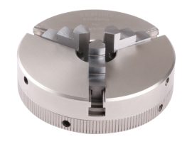
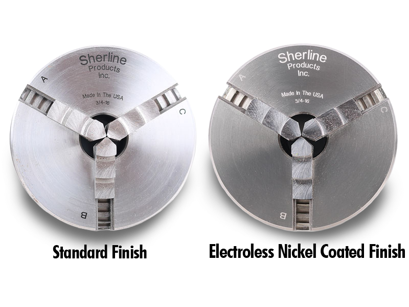
Optional Electroless Nickel Spindles
Most of our spindles are available with a Electroless Nickle plating as a rustproof option for an additional cost. Check the option box above to add the Electroless Nickel plating to your spindle order.
These spindles should be considered light duty. A .405 (10 mm) through hole allows long stock to be passed through the spindle. This design provides a lot of versatility but was not intended for long or out-of-round parts to be rotated at high RPM. It is up to the operator to determine if the spindle and the setup are adequate and safe for the job being attempted.
The spindle is equipped with a dust cover, but it is not totally sealed. The presence of dust from grinding operations can shorten bearing life considerably. It was also not designed to be operated in a coolant bath. The spindle shaft should be shielded from coolant spray.
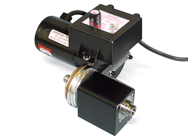
About the 90-Volt DC Motor
The powerful DC motor offers its maximum torque at low RPM, where you need it most in machining. This means it offers far more useable power than an AC/DC motor of equivalent or larger size. It also offers smoother and quieter operations than an AC/DC motor. The V-step pulley has two positions: A high-speed, low-torque position, and a low-speed, high-torque position. The second pulley position lowers the speed range down to about half that of the pulley position.
Standard Motor Features
- 1/2 HP 90-volt high-torque DC motor (single direction)
- 2-step “V” belt pulley (2nd position for more torque at low RPM)
- Fiberglass-reinforced urethane drive belt
- Variable speed electronic speed control: 70-2800 RPM
- Load compensating circuit keeps RPM constant
- Speed control accepts any input from 100 VAC to 240 VAC, 50 or 60 Hz, and automatically converts it to 90V DC output to the motor
- Eight-foot, three-wire power cord (Select the correct wall plug or converter for your region)