Product Description
About the 18″ Base CNC-Ready Mill with Ball Screws
This machine is based on our 18″ NexGen 5800-series mill. The 18″ mill base with ball screws comes with all-new saddles developed for the ball screws and #23 NEMA frame stepper-motor mounts with high-torque couplings.
The X/Y-mill saddle has been beefed up to accommodate the larger ball screws, and it has an electroless nickel/Teflon coating. This coating offers a hard surface that is rustproof, while the Teflon provides a friction coefficient of .1-.2u for smoother movement of the saddle and the table.
The new ball screw design for the column saddle reduces the overall Z-axis travel by 1.4″. Because the ball nut does not allow the column saddle to move down as far as the old style column saddle, we made the new ball screw column saddle longer. This will allow you to move the headstock closer to the top of the mill table. However, you will still lose 1.4″ of overall travel in the Z-axis.

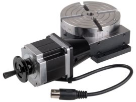
R: 18″ ball leadscrew mount
Click on the image for a larger view.
The Z-axis column bed on the 18″ ball screw mill is mounted directly to the swing arm with an arm mount, unlike the 5800 NexGen mill that utilizes a movable clamping disk. This effectively eliminates the side-to-side rotational axis of the column bed.
The Axes of Movement of a Sherline 6858 Ball Screw Mill
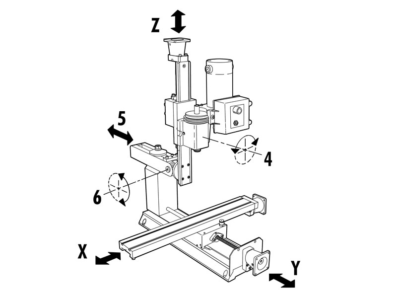
The table left/right movement is referred to as the X-axis. The table in/out movement is the Y-axis. Headstock up/down movement is referred to as the Z axis. The headstock can also be rotated on its saddle on Sherline mills (#4), the column ram can be moved in and out (#5), and the Z-axis column can be tilted forward and back (#6).
- Rolled Ball Screw with BSH Nut
- 10mm Diameter, 2mm Lead
- C7 Accuracy*, P1 Preload
*C7 accuracy has a linear tolerance of 50 micrometers / 300mm or .002″ / 12.0″.
The ball screws are only available in metric, so the numeric graduations on the handwheel dials are 2mm per revolution and .02mm per line.
Standard equipment for the model 6858 CNC-ready mill includes:
- A powerful 90V DC motor with electronic speed controller
- 18″ base
- Electroless nickel/Teflon coated mill saddle
- 18.0″ (457 mm) x 2.75″ (70 mm) table with two T-slots
- 7″ x 13″ tooling plate with three T-slots
- 15″ mill column bed with nickel/Teflon coating
- Stepper-motor mounts with high-torque couplings
- The handwheels are included and can be mounted to the end of the stepper motors to maintain manual control when needed.* 2-1/2″ (63mm) adjustable “zero” handwheel on the Z-axis and 2″ (51mm) adjustable “zero” handwheels on the X- and Y-axes. Each handwheel has laser-engraved aluminum handwheel collars
*NOTE: CNC-ready machines cannot be operated manually unless double-shaft stepper motors are installed. - ¼” Drill Chuck w/ key, #1 Morse arbor with drawbolt
- Pulleys, drive belt, three hexagonal keys, spindle bars, gib removal tool, eight-foot three-wire power cord, and instruction manual
- Oil reservoirs on the X/Y axes and the Z-axis to help keep critical parts lubricated.
- Brass leadscrew cover that keeps chips off the rear of the Y-axis leadscrew
- Accordion way cover