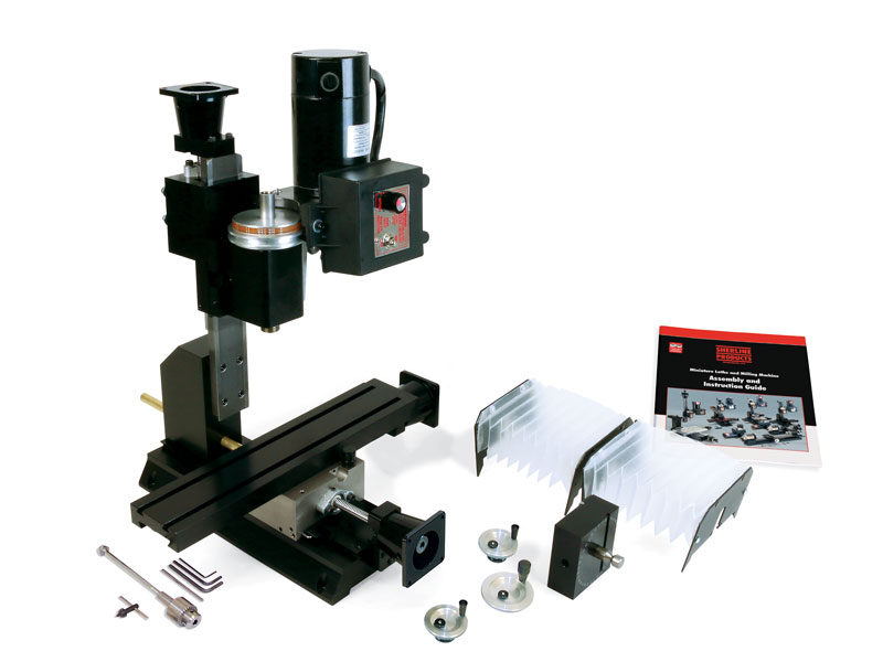
Product Description
About the 12″ Base CNC-Ready Mill with Ball Screws
This machine is based on our popular 12″ Deluxe 5400-series mill. The 12″ mill base with ball screws comes with all-new saddles developed for the ball screws and #23 NEMA frame stepper-motor mounts with high-torque couplings.
The X/Y-mill saddle has been beefed up to accommodate the larger ball screws, and it has an electroless nickel/Teflon coating. This coating offers a hard surface that is rustproof, while the Teflon provides a friction coefficient of .1-.2u for smoother movement of the saddle and the table.
The new ball screw design for the column saddle reduces the overall Z-axis travel by 1.4″. Because the ball nut does not allow the column saddle to move down as far as the old style column saddle, we recommend upgrading to the 15″ mill column. This will allow you to move the headstock closer to the top of the mill table. However, you will still lose 1.4″ of overall travel in the Z-axis.
SPECIAL NOTE ON THE COLUMN BED: The new column saddle on the Z-axis is longer, and the headstock mounts towards the bottom of the saddle. We did this because the column saddle Z-axis ball nut mount (P/N 45046) would not allow the original saddle to move low enough to the top of the mill table. Additionally, the P/N 45046 reduces the overall amount of usable Z-axis travel, and the maximum clearance above the table will be 2″ less than that of a standard leadscrew machine. In order to achieve greater travel and clearance above the table, we suggest that you upgrade to the 15″ Extended Mill Column Bed (P/N 45261) if you are ordering a new machine or doing a mill ball screw retrofit. The 15″ extended column bed makes up for the loss of travel in the Z-axis. It is also available with an electroless nickel/Teflon plating (P/N 45265) that adds increased lubricity and rust prevention.
- Rolled Ball Screw with BSH Nut
- 10mm Diameter, 2mm Lead
- C7 Accuracy*, P1 Preload
*C7 accuracy has a linear tolerance of 50 micrometers / 300mm or .002″ / 12.0″.
The ball screws are only available in metric, so the numeric graduations on the handwheel dials are 2mm per revolution and .02mm per line.
Standard equipment for the model 6854 CNC-ready mill includes:
- A powerful 90V DC motor with electronic speed controller
- 12″ base
- Electroless nickel/Teflon coated mill saddle
- 13.0″ (330 mm) x 2.75″ (70 mm) table with two T-slots
- 11″ standard mill column bed (Option to upgrade to a 15″ mill column bed with nickel/Teflon coating is available)
- Headstock spacer block
- Stepper-motor mounts with high-torque couplings
- The handwheels are included and can be mounted to the end of the stepper motors to maintain manual control when needed.* 2-1/2″ (63mm) adjustable “zero” handwheel on the Z-axis and 2″ (51mm) adjustable “zero” handwheels on the X- and Y-axes. Each handwheel has laser engraved aluminum handwheel collars
*NOTE: CNC-ready machines cannot be operated manually unless double-shaft stepper motors are installed. - ¼” Drill Chuck w/ key, #1 Morse arbor with drawbolt
- Pulleys, drive belt, three hexagonal keys, spindle bars, gib removal tool, eight-foot three-wire power cord, and instruction manual
- Oil reservoirs on the X/Y axes and the Z-axis to help keep critical parts lubricated.
- Brass leadscrew cover that keeps chips off the rear of the Y-axis leadscrew
- Accordion way cover