


|
|
Always wear safety glasses when operating machine tools. |
|
Download PDF Assembly and Instruction Guide
|
Download PDF 2000/2010 Mill Set-up Instructions
|
|
2000-series Mill Z-axis Installation instructions
|
Download PDF 14″ Mill Base Dimensions
|
|
Download PDF Mill Saddle Lubrication instructions
|
Back to Manually Controlled Mills
Sale!
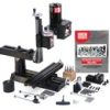
14″ 8-direction Mill
The Deluxe 8-Direction Milling Machine is one of the most versatile mills Sherline offers. In addition to standard X-, Y-, and Z-axis movement, this model provides five additional directions of headstock adjustment—allowing you to position the spindle for drilling or milling operations from nearly any angle.
- The headstock pivots up to 90° left or right.
- The column bed also rotates side to side up to 90°, enabling angled drilling.
- A specialized knuckle joint allows the column to tilt front to back.
- The ram-style column base can swing side to side up to 90°, offering even greater flexibility.
- Loosening the column cap lets the ram move in and out, providing over 5.5″ of additional travel.
With this wide range of movement, the machining possibilities are nearly limitless within the compact work envelope of the machine. The 14″ base also increases Y-axis travel by 2″ compared to the Model 5400 mill, making it a powerful tool for advanced miniature machining applications.
The 8-direction benchtop mill is ideal for users who need a small, precision milling machine capable of high-accuracy work. Like all Sherline mills, it is made in the USA and supported by unmatched customer service. Despite its compact size, this 14″ benchtop mill is engineered to handle wood, plastic, aluminum, and even steel—delivering full-size machine precision in a desktop footprint.
Note on Ordering a Metric Mill – Most Sherline cutting tool, such as center drills, are offered in fractional sizes. If you opt for a metric machine with metric collets or holders, you’ll need to order compatible fractional-size holders to use these tools effectively.
Standard Equipment for the 8-Direction Benchtop Mill
- A powerful 90V DC motor with electronic speed controller
- 14″ base with laser-engraved scales
- Brass leadscrew cover that keeps chips off the rear of the Y-axis leadscrew
- 2.75″ (70 mm) x 13.0″ (330 mm) table with laser-engraved scales and two T-slots
- 2″ column riser block
- Resettable, zero-adjustable handwheels:
- (2) 2″ (51 mm) handwheels on X- and Y-axes
- (1) 2-1/2″ (63 mm) handwheel on Z-axis
- All with laser-engraved aluminum collars
- ¼” Drill Chuck w/ key, #1 Morse arbor with drawbolt
- Pulleys, drive belt, three hexagonal keys, spindle bars, gib removal tool, eight-foot three-wire power cord, and instruction manual
- Oil reservoirs on the X/Y axes and the Z axis help keep critical parts lubricated. These were initially developed for CNC machines that run constantly for hours on end but can benefit manual machines as well
-


Related products
Sale!
 From: Original price was: $2,746.59.$2,197.27Current price is: $2,197.27.
Select options
This product has multiple variants. The options may be chosen on the product page
From: Original price was: $2,746.59.$2,197.27Current price is: $2,197.27.
Select options
This product has multiple variants. The options may be chosen on the product page
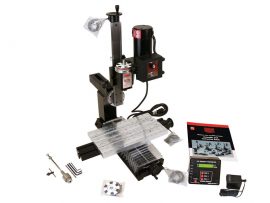
18″ Mill with DRO
The 18" DRO Benchtop Mill includes a digital readout system and special handwheels with built-in electronic encoders that replace the standard handwheels (standard handwheels are not included with the DRO option). These encoders connect directly to the digital readout box, which displays precise table travel for all three axes. The readout can be zeroed at any time with the push of a button, and spindle RPM is constantly displayed while the motor is running. The DRO system is compatible with both inch and metric machines.
This compact DRO mill is perfect for users who need to produce small, high-precision parts. As with all Sherline milling machines, it’s made in the USA and supported by industry-leading customer service. Despite its size, the DRO mill can accurately cut wood, plastic, aluminum, and steel—delivering full-size machining capabilities in a desktop-sized footprint.
Using the DRO System
The DRO displays each axis position relative to a zero point you set.
- Inch models show position to 0.0005" (three and a half decimal places)
- Metric models show position to 0.01 mm
The system supports both ball screw and leadscrew machines. As well as the ability to use Metric DROs on inch machines or inch DROs on metric machines. It features six selectable modes based on machine type (mill or lathe), screw type (leadscrew or ball screw), and preferred display units (inch or metric). For setup instructions, refer to the official DRO Mode Instructions.
You can electronically compensate for backlash by inputting the measured backlash value for each axis. When the direction of handwheel rotation reverses, the DRO subtracts the backlash before updating the position—eliminating common errors and making it easier to track travel distance and direction. The power supply automatically switches between 120V and 240V, making it suitable for use in countries with 220–240V electrical current. A socket adapter may be required outside North America.
Notes on Ordering a Metric Mill – Most of our cutting tools, such as center drills, are manufactured in fractional sizes. If you’re using a metric machine with metric collets or end mill holders, you’ll need to order fractional holders to fit these tools.Standard Equipment for the DRO NexGen Benchtop Mill
- Powerful 90V DC motor with electronic speed control
- 18″ mill base with Y-axis leadscrew protection
- 2.75″ (70 mm) × 18.0″ (457 mm) extended mill table with two T-slots
- 7″ × 13″ tooling plate
- 15″ (63 mm) extended column bed
- Extra-rigid column base
- Digital readout box with LCD display, RPM sensor, power supply, cables, stand, and all necessary mounting hardware. No hole drilling is required to mount.
- DRO handwheels that can be reset to zero electronically with the push of a button on the DRO display box.
- (2) 2″ (51 mm) DRO handwheels on X- and Y-axes
- (1) 2-1/2″ (63 mm) DRO handwheel on Z-axis
- All with laser-engraved aluminum collars
- ¼” drill chuck with key, #1 Morse arbor, and drawbolt
- Oil reservoirs on the X-, Y-, and Z-axes
- Pulleys, drive belt, three hex keys, spindle bars, gib removal tool, 8-foot three-wire power cord, and instruction manual
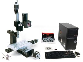
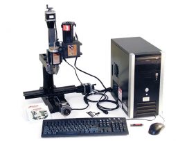
18″ NexGen CNC Benchtop Mill System Package A
Discover the Sherline 8580, a high-precision CNC vertical machining center designed for detailed and complex projects. Ideal for both professionals and hobbyists, this mill offers superior accuracy and control for a wide range of machining tasks.
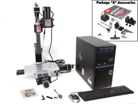
14″ 8-direction CNC Benchtop Mill System
Enhance your machining capabilities with the Sherline 8020 Vertical Machining Center. This CNC mill delivers exceptional precision and control, making it perfect for detailed projects in both hobbyist and professional workshops.