Product Description
Steel Bed on Raised Base
- The steel bed has ground dovetails and is available with either an inch or metric leadscrew.
- The leadscrew is precision rolled from steel and is located under the table, out of the way of chips. Leadscrew backlash is adjustable.
- 2″ Industrial handwheel is graduated in .001′ increments on inch slides and in .01 mm increments on metric slides.
Base Mounting Provisions
FROM THE BOTTOM—Two 1/4-20 holes are provided in the base’s bottom on 2-inch centers for mounting.
FROM THE TOP—If access is not available from the bottom, the slide can be mounted from the top using the four provided angle clamps. They slide into the groove around the perimeter of the base, and holes are drilled in the mounting surface and tapped to accept the 10-32 socket head cap screws provided. Use all four clamps for the most secure mount.
Standard Headstock Features
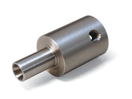
- The headstocks are made from extruded 6061-T6 aluminum and have a black anodized finish. They are available with your choice of a spindle (3/4-16 #1M taper or an ER-16*).
- A brass gib on the dovetailed base fits Sherline steel dovetailed bed and column material
- Spindle bearing dust cover washer
- ER-16 collet nut ships with the ER-16 spindle headstocks*
*NOTE: We do not sell the collets used with the ER-16 spindle. Those are available through MSC Industrial Supply Co. or other tool supply sources.
Optional Nickel/Teflon Spindles
Most of our spindles are available with a Nickle/Teflon plating as a rustproof option for an additional cost. Check the option box above to add the Nickel/Teflon plating to your spindle order.
Spindle Precautions
These spindles should be considered light duty. A .405 (10 mm) through hole allows long stock to be passed through the spindle. This design provides a lot of versatility but was not intended for long or out-of-round parts to be rotated at high RPM. It is up to the operator to determine if the spindle and the setup are adequate and safe for the job being attempted.
The spindle is equipped with a dust cover, but it is not totally sealed. The presence of dust from grinding operations can shorten bearing life considerably. It was also not designed to be operated in a coolant bath. The spindle shaft should be shielded from coolant spray.
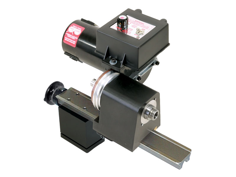
About the 90-Volt DC Motor
The powerful DC motor offers its maximum torque at low RPM, where you need it most in machining. This means it offers far more useable power than an AC/DC motor of equivalent or larger size. It also offers smoother and quieter operations than an AC/DC motor. The V-step pulley has two positions: A high-speed, low-torque position, and a low-speed, high-torque position. The second pulley position lowers the speed range down to about half that of the pulley position.
Standard Motor Features
- 1/2 HP 90-volt high-torque DC motor (single direction)
- 2-step “V” belt pulley (2nd position for more torque at low RPM)
- Fiberglass-reinforced urethane drive belt
- Variable speed electronic speed control: 70-2800 RPM
- Load compensating circuit keeps RPM constant
- Speed control accepts any input from 100 VAC to 240 VAC, 50 or 60 Hz, and automatically converts it to 90V DC output to the motor
- Eight-foot, three-wire power cord (Select the correct wall plug or converter for your region)