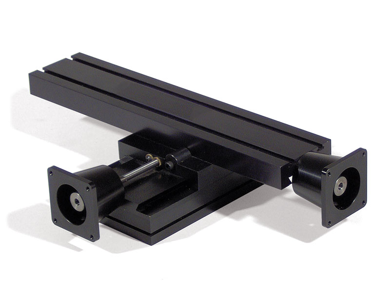
CNC-Ready 2-Axis X/Y Machine Slide

-

2-axis CNC-ready machine slides available with table lengths of 13″ or 18″.
Select your table size and unit type for pricing.

Clear selection
    Reset options

Product Description

About the CNC-Ready 2-Axis Machine Slides

The Sherline industrial 2-axis slide was developed from components of the X/Y base of the Sherline miniature milling machine. The movements are designated as the X-axis and the Y-axis like a milling machine. The Y-axis moves the table in and out. The X-axis moves the table from side to side. If the table is mounted vertically, the side-to-side travel is still called the X-axis, but the vertical travel would then be called the Z-axis.

  1. The slides are manufactured from 6061-T6 aluminum and finished with a black anodized coating.
  2. The 2-axis CNC-ready machine slides are available with table lengths of 13″ or 18″, and any table is available with either an inch or metric leadscrew.
  3. Leadscrews are precision rolled from steel, and table screws are located under the table, out of the way of chips. Leadscrew backlash is adjustable.
  4. Dovetailed tables and saddles have adjustable gibs to eliminate play.
  5. 1-5/8″ handwheels are graduated in .001″ increments on inch slides and in .01 mm increments on metric slides.
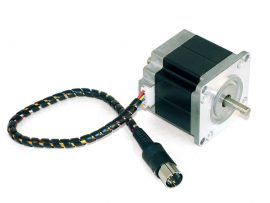
  6. Stepper motor mounts for NEMA 23 stepper motors

NOTE: CNC-ready slides cannot be operated manually until stepper motors are installed.

Mounting Provisions

FROM THE BOTTOM—Four 1/4-20 holes are provided in the base’s bottom on 2-inch centers for mounting.

FROM THE TOP—If access is not available from the bottom, the slide can be mounted from the top using the four angle clamps provided. They slide into the groove around the perimeter of the base, and holes are drilled in the mounting surface and tapped to accept the 10-32 socket head cap screws provided. Use all four clamps for the most secure mount.

Weight Capacity

Our slides’ weight capacity is about 10 lbs. depending on where the weight is located and how long the table is. On an 18″ table, you should not go more than 10 lbs. of weight at the end of the table (there is a leverage factor). If the weight is more centrally located (closer to the base), you can exceed the 10 lbs. limit.

Duty Cycle

Under heavy constant use, the dovetail area of the slide will start to show some wear on the anodize after one year (2080 hours). They are still fully functional at this point, but the anodized coating will begin to wear thin. The dovetail and the screw will last longer if you keep them lubricated with light oil*.

The leadscrews have a rolled thread which is hardened a bit by the rolling process. The backlash nuts are brass. The nut is the softer material, and therefore it is the part that wears out. The backlash nut is adjustable, so it can compensate for the wear until the threads are gone. You should get the same duty cycle (2080 hours) from the backlash nut before it will need to be adjusted or replaced.

*NOTE: Do not use WD40 as a lubricant on these slides. WD40 will remove the anodized coating from these parts!

warning-symbol
The improper use of machine tools and their accessories can result in serious injury. Before using this tool, thoroughly read the instructions and make sure you understand its proper and safe use.

safety-glasses-symbol

Always wear safety glasses when operating machine tools.

Download PDF 6540 Instructions

Instructions PDF Download

6545 (6546) 13″ table 6545-18 (6546-18) 18″ table
Table size 13″ x 2.75″ (330 mm x 70 mm) 18″ x 2.75″ (458 mm x 70 mm)
Table height 2.8″ (71.1 mm) 2.8″ (71.1 mm)
X-axis travel 9.0″ (228 mm) 13.38″ (340 mm)
Y-axis travel 4.1″ (104 mm) 4.1″ (104 mm)
Hold-down provision 2 T-slots* 2 T-slots*
Mounting provision 4 holes 1/4-20 in the bottom of the base plus slot for angle clamps 4 holes 1/4-20 in the bottom of the base plus slot for angle clamps
Handwheel 1-5/8″ laser engraved aluminum with two pre-loaded ball bearings 1-5/8″ laser engraved aluminum with two pre-loaded ball bearings

* NOTE: Sherline 10-32 T-nuts that fit the table T-slots are available in a package of 10 as P/N 3056.

Part No. Description Quantity
12050 8-32 X 3/8″ Socket Head Cap Screw (+ 2 zip ties) 6
35580 Hold-down clamp 4
40280 Thrust collar (18″ table only) 1
40510 10-32 x 3/8″ Socket Head Cap Screw 2
40520 10-32 x 3/16″ Cup Point Set Screw 6
40530 5-40 X 3/8″ Socket Head Cap Screw (18″ table only) 1
40550 5/32″ hex key 1
40570 3/32″ hex key 1
40600 10-32 X 1/4″ Flat Point Set Screw 2
40690 10-32 x 3/4″ Socket Head Cap Screw 1
40760 Thumbscrew 1
40820 Gib Lock 2
40890 (41890 Metric) X-axis Slide Screw Nut 1
40890 Gib 2
45070 Teflon® Lock 1
50130 (51130 Metric) X-axis Anti-backlash Nut 1
50140 (51140 Metric) Y-axis Anti-backlash Nut 1
50150 Backlash Lock Star Gear 2
50161 (51161 Metric) Y-axis Leadscrew 1
50171 (51171 Metric) 13″ X-axis Leadscrew (P/N 6545/6546) 1
50173 (51173 Metric) 18″ X-axis Leadscrew (P/N 6545-18/6546-18) 1
50190 Table Lock 1
50200 (51200 Metric) Y-axis Slide Screw Nut 1
50211 Button Head Socket Screw 2
50910 Mill Saddle 1
50920 Mill Saddle Oiler Body 1
50930 Mill Saddle Oiler Cap 1
54182 18″ Mill Table (P/N 6545-18/6546-18) 1
54183 18″ Table Leadscrew Bushing (P/N 6545-18/6546-18) 1
65401 Industrial X/Y Base 1
67102 Stepper Motor Mounts 2
67050 13″ Mill Table (P/N 6545/6546) 1
671052 CNC Coupling 2
67106 (67108 Metric) X-axis Preload Nut (Rh) 1
67107 (67109 Metric) Y-axis Preload Nut (RH) 1
67111 8-32 X 3/4″ Socket Head Cap Screw 4
67115 5-40 x 7/8″ Socket Head Cap Screw 2
67120 CNC Preload Bearing 4

Click the P/Ns below to download a zipped version of the IGS 3D CAD file. You will need to extract the zip file before viewing the IGS file.
13″ 6545/6546 CNC-Ready 2-Axis Slide 3D IGS model
18″ 6545-18/6546-18 CNC-Ready 2-Axis Slide 3D IGS model
You need an IGS viewer to view .igs files. CLICK HERE to download a FREE IGS viewer.