18″ Benchtop Mill XYZ Base w/ Ball Screws _ CNC-Ready

-

2 to 4-week lead time

  • *Preferred unit of measurement for laser engraved portions
    Please note that our ball screws only come in a metric pitch
  • *Will you be using Sherline’s CNC driver box?

Purpose of the Sherline Mill XYZ Bases

The Sherline ball screw mills can be purchased without the headstock and motor/speed control. This allows owners of other Sherline machines to swap the headstock and motor/speed control from one machine to the ball screw mill in approximately 60 seconds. This package offers a savings compared to the price of our full ball screw mills.

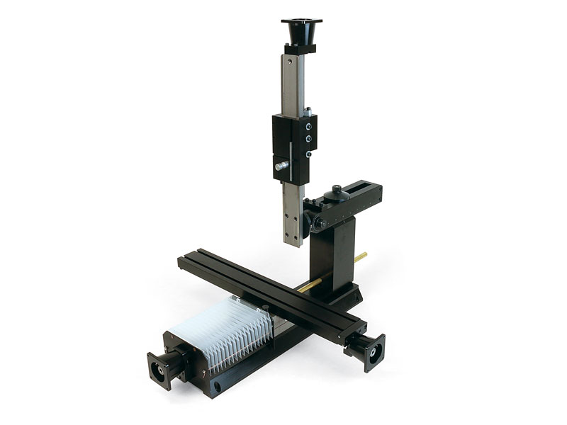
The Axes of Movement of a Sherline 6858 Ball Screw Mill

Click on the image for a larger view.

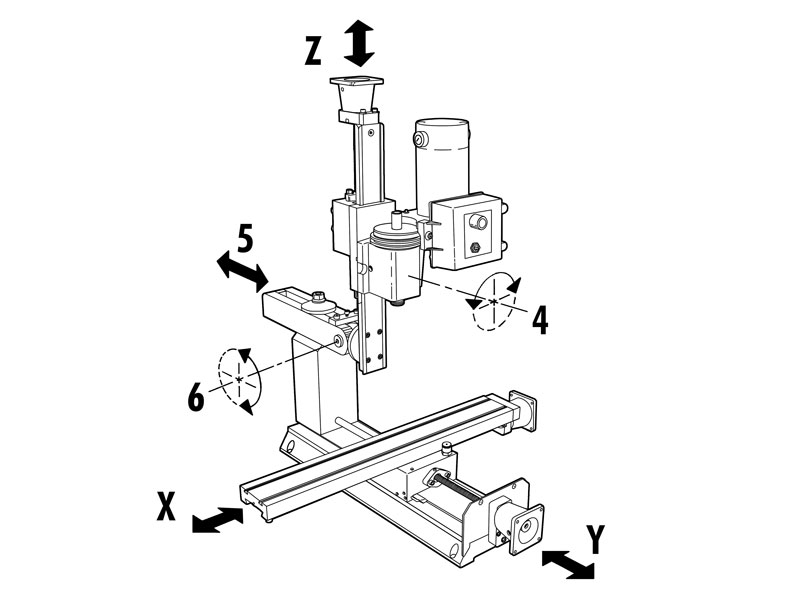
The table left/right movement is referred to as the X-axis. The table in/out movement is the Y-axis. Headstock up/down movement is referred to as the Z axis. The headstock can also be rotated on its saddle on Sherline mills (#4), the column ram can be moved in and out (#5), and the Z-axis column can be tilted forward and back (#6).

Standard equipment for the 685801 XYZ base:

  • 18″ Mill Base
  • Electroless nickel/Teflon coated mill saddle
  • 15″ Extended Column Bed with nickel/Teflon plating
  • Extra-Rigid Column Base
  • 18″ Extended Mill Table
  • Stepper-motor mounts with high-torque couplings
  • The handwheels are included and can be mounted to the end of the stepper motors to maintain manual control when needed.* 2-1/2″ (63mm) adjustable “zero” handwheel on the Z-axis and 2″ (51mm) adjustable “zero” handwheels on the X- and Y-axes. Each handwheel has laser engraved aluminum handwheel collars
    *NOTE: CNC-ready machines cannot be operated manually unless double-shaft stepper motors are installed.
  • Oil reservoirs on the X/Y axes and the Z-axis to help keep critical parts lubricated.
  • Brass leadscrew cover that keeps chips off the rear of the Y-axis leadscrew
  • Accordion way cover
  • Travel: X=13.65″ (347 mm), Y= 11.0″ (279 mm), Z=9.25″ (235 mm)

warning-symbol
The improper use of machine tools and their accessories can result in serious injury. Before using this tool, thoroughly read the instructions and make sure you understand its proper and safe use.

safety-glasses-symbol

Always wear safety glasses when operating machine tools.

Download PDF Assembly and Instruction Guide

Instructions PDF Download

Download PDF 5201 Instructions

Instructions PDF Download

Download PDF 6858 Exploded View

Instructions PDF Download

Download PDF Ball Screw Mill Unpacking and Assembly Notice

Instructions PDF Download

Download PDF 5920/5958 Ball Screw Way Cover Instructions

Instructions PDF Download

Download Lubrication for Ball Screw Machines PDF

Instructions PDF Download

Download Ball Screw Lubrication PDF

Instructions PDF Download

Travel, X-Axis 12.80″ (325.1mm)
Travel, Y-Axis 11.00″ (279 mm)
Travel, Z-Axis 9.25″ (235 mm)
Width Overall 20.375″ (518 mm)
Depth Overall Base footprint: 21.125″ (537 mm); With fully extended brass leadscrew cover: 28.375″ (721 mm)
Height Overall (Max.) 26.5″ (673 mm)
Table size 2.75″ x 18.00″ (70 x 457 mm)
Hold-down provision 2 T-Slots (3 T-Slots with optional 7″ x 13″ tooling plate P/N 3562)
Movements in addition
to X-, Y- and Z-axes
Headstock rotation (90° left/right), Column pivot (90° Fwd/Bk), Column travel (In/Out) 5.5″ (140 mm)
Shipping Weight 72 lb. (32.73 kg)
For optimal performance, we recommend using the High-Torque Stepper Motors with our Ball Screws.