Always check the voltage setting before starting a computer for the first time
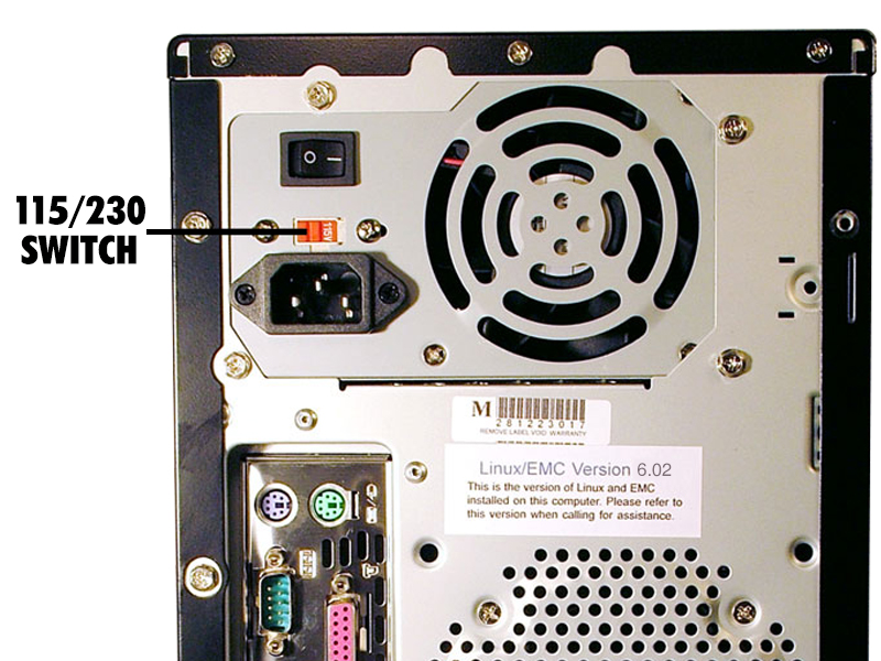
Your new Sherline CNC computer should come with the voltage pre-set to the proper value for your location; however, it is always best to confirm this setting before powering up the computer for the first time. Moving to another country or purchasing a used system from another country are typical reasons the settings might need to be changed. The main voltage setting switch is on the back of your computer. The driver box power supply located inside your computer contains a second voltage selection switch that is set to the same value as the one on the back of the computer. If you need to change one, you will need to change the other as well.
In order to protect components inside the computer from damage, Sherline has placed a tamper-proof label across the panel joint. Once removed it leaves marks and cannot be replaced. Opening this panel may void your warranty unless you were instructed by Sherline to do so. To assure your warranty remains in place, please contact Sherline before opening the computer case.
Opening the Computer Case
Click on any photo to view a larger image.
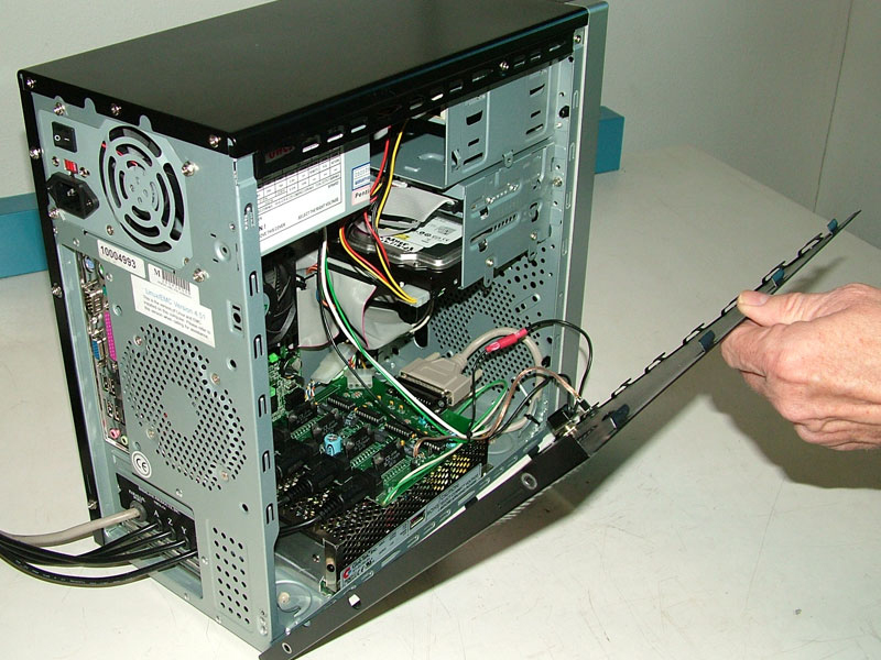
After contacting Sherline, the components in the computer are accessed from the left side of the case (when viewed from the front). Shown below are the steps to safely access your computer to change the driver box voltage selection switch. Older Sherline computers may not have the tamper-proof label, but we still suggest you contact Sherline before attempting to open your computer.
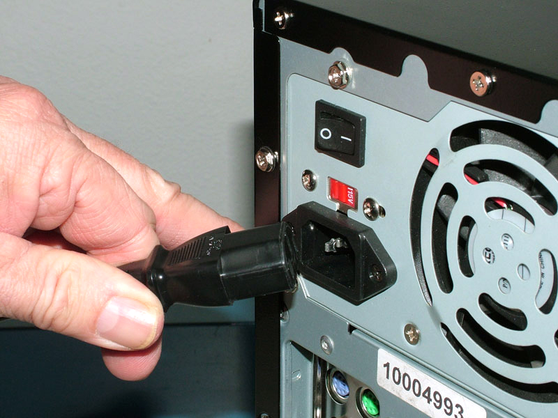
CAUTION—ELECTRICAL HAZARD!: As long as a computer is plugged in, some components inside have the potential for electrical shock even with power to the computer in the OFF position. Always make sure the computer is physically unplugged before opening the case.
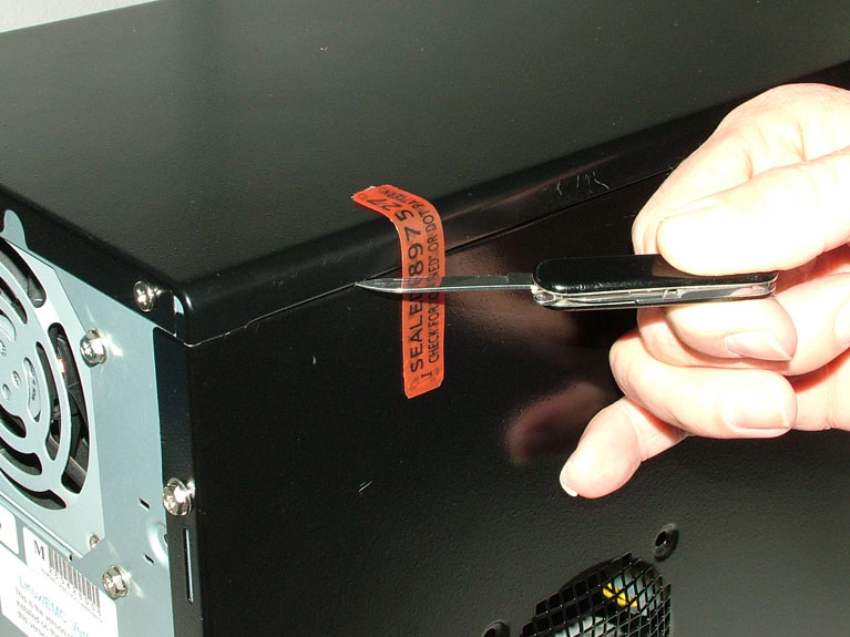
Slit or peel off the tamper-proof label where it seals the access door. (Contact Sherline before doing so or you could void your warranty.)
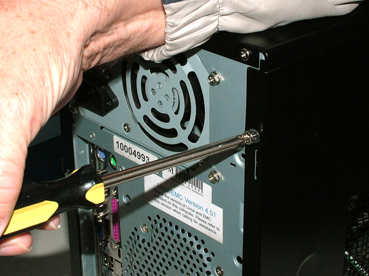
Remove the two screws that secure the access door to the computer case. They are located on the top and bottom of the access cover where it wraps around the back of the case.

4.
Slide the access door about 1/2″ toward the rear of the case to disengage.

5.
Keeping the bottom of the door near the bottom of the computer case, lower the top of the access door away from the computer so it can be laid down flat. This keeps from putting undue stress on the wires that connect the power switch and LED that are attached to the door. Make sure the wire to the LED does not come unplugged. Sometimes there is barely enough wire to lay the panel cover down without pulling on this wire.*
*NOTE: If the wire to the red LED power indicator light should be accidentally disconnected, it must be reinstalled in the same orientation as it was before. If the LED light does not work when power is turned on to the stepper boards, it means it has either come unplugged or was re-connected backwards. You will have to open the case again, unplug the wire, rotate the connection 180° and reconnect it.
6.
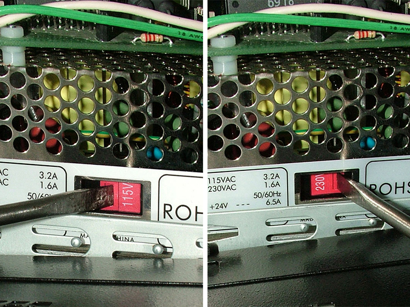
Locate the red 115/230V selection switch near the center bottom of the power supply under the driver board at the bottom of the computer case. It is operated just like the one on the back of the computer case. It is slightly recessed, so you may need to use the blade of a small screwdriver to change the switch position. Whatever number you can read is the setting. Changing the setting will expose the other number.
7.
Carefully close the case in the reverse order, being careful not to pinch any of the wires in the process. Make sure the wire to the LED has not become disconnected.