Sherline 9/16″ Through-Hole Spindle Headstocks

-

Select your bearing and motor options for pricing.

Clear selection
    Reset options

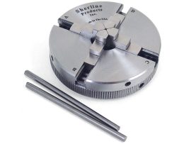
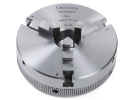
About Sherline’s 9/16″ Through-Hole Spindle Headstock

We opened the spindle through-hole to a maximum of 9/16″ (14.28 mm). While this allows larger stock to pass through the headstock, it also eliminates the #1 Morse internal taper, meaning tapered tools like drill chucks, fly cutters, etc., cannot be held in the headstock. Threaded tools can still be used, such as 3 or 4-jaw chucks and end mill holders. The headstock includes a spindle pulley and a precision ground head key.

NOTE: Certain attachments, like the Thread Cutting Attachment, the Lathe Power Feed, and the 10,000 RPM Pulley Set, will NOT work with the 9/16″ Collet Headstock. If you are uncertain if an accessory will work with the 9/16″ Collet Headstock, please call for more information.

Custom Build Your 9/16″ Through-Hole Spindle Headstock with the Following Options:

  • Class 3 or Class 5 Bearings
  • With or without a DC Motor and Speed Control Unit

NOTE: The 9/16″ spindles DO NOT have electroless nickel plating as an available option.
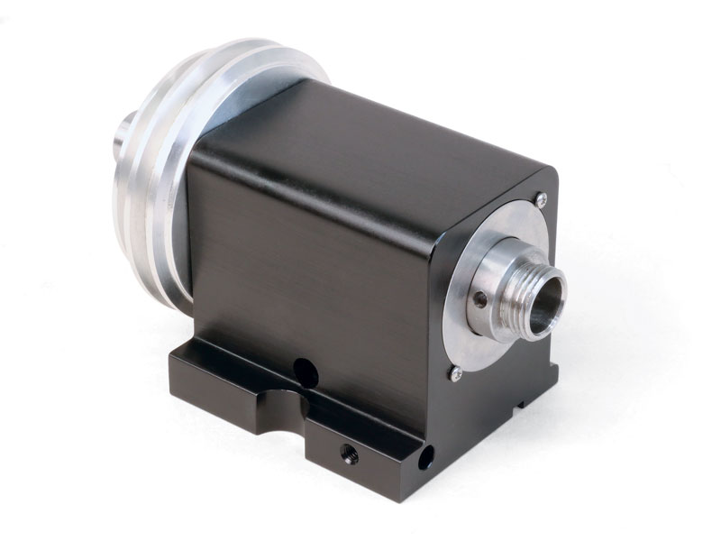
Bearing Options

The bearings in the headstocks are offered in two classes: C3 and C5.

The C3 bearings have been standard in all of our headstocks for years and have proven reliable over that time.

The C5 bearing headstocks come at a higher price than the standard C3 bearings headstocks, but they run smoother, quieter, and cooler than our regular class 3 bearing headstocks and are more suitable in an industrial setting.

Sherline’s new C5 headstocks feature two 20 mm, class 5, lifetime-lubricated ball bearings with an adjustable preload nut. The preload is adjusted at the factory to .0002″ (.005 mm) of endplay. The preload adjustment is controlled by the outer races of the bearings being held apart by the headstock case and the inner races being pulled together by the preload nut. This is appropriate for extended running at speeds of 4000 RPM or less. You may need a slightly looser preload setting of .0003″ for operating speeds up to 10,000 RPM.

Optional DC Motor with Speed Control

You can order your headstock with or without our DC motor and speed control unit.

The powerful DC motor offers its maximum torque at low RPM, where you need it most in machining. This means it provides far more useable power than an AC/DC motor of equivalent or larger size. It also offers smoother and quieter operations than an AC/DC motor.

A sophisticated speed control unit powers and controls the motor. The speed control unit accepts any incoming AC current from 100 VAC to 240 VAC, 50 or 60 Hz, and automatically outputs 90V DC to the motor so that this unit can be used anywhere in the world without a transformer. All you need is the correct wall plug or converter. Once the on/off switch is switched to the “ON” position, a speed control knob is used to vary the entire range’s speed. With the pulley in the “normal” position, the speed range is about 70 to 2,800 RPM. In the “high torque” position, the maximum speed is cut in half, but torque at any given speed is much greater*.

*NOTE: The full torque at the lower RPM range of 70-1,400 will be obtained when the motor pulley belt is in the low-speed/high-torque pulley groove. The high-speed pulley groove will have full torque in the 1,200 to 2,800 RPM range.

warning-symbol
The improper use of machine tools and their accessories can result in serious injury. Before using this tool, thoroughly read the instructions and make sure you understand its proper and safe use.

safety-glasses-symbol

Always wear safety glasses when operating machine tools.

Download PDF DC Motor Instructions

Instructions PDF Download

Download PDF DC Motor Wiring Instructions

Instructions PDF Download

Headstock Specifications
Spindle Specifications
Headstock spindle nose 9/16″ Through-hole
Headstock spindle external thread 3/4 x 16
Pulley groove side angle 19°
Allowable Tolerances
Spindle Runout (at spindle nose), Maximum allowable (Most are within .0005″) 0.001″
Spindle End Play (adjustable with preload nut), Factory Settings 0.0002″
Headstock Bearings
Designation/stock number (ZZ refers to “double shielded”) 6004ZZ
Size of bore 20 mm (0.7874″)
Tolerance of bore 0.0004″
Outside Diameter 42 mm (1.6535″)
Tolerance of OD 0.0005″
Width 12 mm (0.4724″)
Bearings 9 balls, 1/4″ Dia.
DC Motor & Speed Control Specifications
Motor and Speed Control ELECTRIC MOTOR SPECIFICATIONS FROM MANUFACTURER
Two-speed pulley RPM range* Normal Belt Position=70-2,800
High-Torque, Low RPM Position=70-1,280
Type of enclosure Totally enclosed, non-vented
Duty rating Continuous–10 oz. in. at 6,100 RPM, .85 amperes; Intermittent–30 oz. in. at 5500 RPM, 1.75 amperes (5 minutes on / 15 minutes off)
Output horsepower .06 KW (60 W) at 10 oz. in. / 6,100 RPM
AC voltage (input) Normally 115 VAC, 60 Hz, Single Phase to rectifier (Sherline electronic speed control converts any input from 100 VAC to 240 VAC, 50-60 Hz.)
DC voltage 90V DC to motor (60 Hz)
Speed in RPM 6,100 RPM continuous
Class of insulation Class A, 105° (C.) insulation system
Normal full load current .85 amperes
Starting current 1.7 amperes instantaneous starting current (<100 milliamperes). This is also stall current in True RMS
Max current at time of changeover from lower speed to higher speed Depends on load
Type of motor 3.00 inch (outer diameter) sub-fractional horsepower brush-type permanent magnet motor
Temperature rise at ambient 50° C. Less than or equal to 45° C.
Motor frame size 3 inches
End use of motor Drive unit for lathe or mill

*NOTE: The full torque at the lower RPM range of 70-1,400 will be obtained when the motor pulley belt is in the low-speed/high-torque pulley groove. The high-speed pulley groove will have full torque at the 1,200 to 2,800 RPM range.

Headstock Bearing Replacement

We don’t recommend that customers replace the headstock bearings. We use custom fixtures to align the spindle and the bearings. You must return your headstock to our facility for bearing replacement*. Contact our customer service department, kim@sherline.com, for an RMA number before sending your headstock back for service.
*NOTE: Fees apply
Click the links below to learn more about the specialized fixtures and procedures for setting the headstock bearing preload.
PDF: Replacing Headstock Bearings
Video: Setting the Headstock Bearing Preload

Headstock Parts
Part No. Description Quantity
31080 10-32 X 3/8″ Set Screw 1
40100 Headstock Casing 1
40169 9/16″ Preload Nut 1
40239 9/16″ Headstock Spindle 1
40260 Precision Ground Head Key 1
40320 Bearing Washer (SS) 1
40330 10-32 X 5/8″ Skt Hd Cap Screw 2
40420* Headstock Class 3 Bearing (*P/Ns 30110 and 3309 only) 2
40410* Headstock Class 5 Bearing (*P/Ns 30106 and 30107 only) 2
40440 #2 X 1/4″ Pan Hd Sheet Metal Screw 2
40520 10-32 X 3/16 Cup Pt Set Screw 1
40540 5/16-18 X 3/4″ Cone Point Set Screw 1
43239 9/16″ Headstock Spindle Pulley 1
Motor Parts* (*P/Ns 30107 and 3309 only)
Part No. Description Quantity
40020 Motor Bracket 1
40040 Drive Belt 1
43000 DC Speed Control Assembly w/Belt Guard 1
43360 Stepped Motor Pulley 1
45475 Hill House DC Motor (2020) 1

Click the P/N below to download a zipped version of the IGS 3D CAD file. You will need to extract the zip file before viewing the IGS file.
30110 9/16″ Headstock 3D IGS Model
You need an IGS viewer to view .igs files. CLICK HERE to download a FREE IGS viewer.