Back to Bar Feeder

Pneumatic Bar Feeder Activation Cylinder Assembly

-

  • *Relay Option

SKU: 8815 Category:

About the Pneumatic Bar Feeder Activation Cylinder Assembly

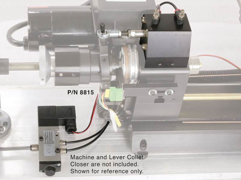
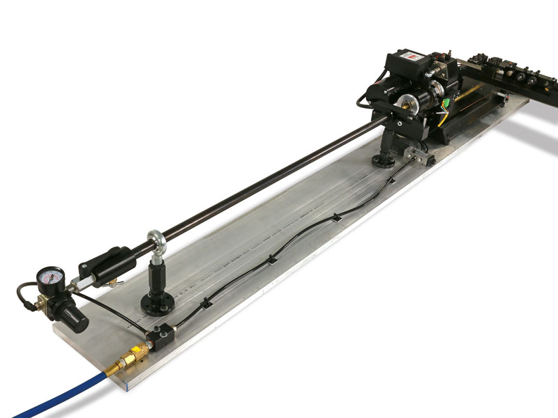
We separated the bar feeder (P/N 8840) into two sections (P/Ns 8815 & 8825) for our customers interested in building their own bar feeder system.

In addition to using this assembly for a bar feeder system, it can also be used as a programmable collet control to open and close the collet. Use M10 and M11 (chuck closed and chuck open, respectively) in your G-code program.

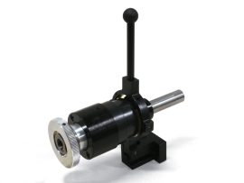
The Pneumatic Bar Feeder Activation Cylinder Assembly is the bar feeder section used in conjunction with our machine and our 3C lever collet closer to open and close the collet pneumatically. Click on the Instructions tab above to download the instructions for this assembly.

NOTE: This system is designed to work with the MASSO Touch control (with the G3 board). If you have an older MASSO G2 board, the G2 board is not compatible with the MASSO “relay module” that is needed. If you use a control system other than the MASSO Touch control, you will need to contact your control manufacturer for compatibility and wiring instructions. Most newer CNC controls are designed to incorporate signals to a relay to control external devices.

The Pneumatic Air Cylinder mounted to a CNC Chucker Lathe (machine not included). Click on the image for a larger view.

warning-symbol
The improper use of machine tools and their accessories can result in serious injury. Before using this tool, thoroughly read the instructions and make sure you understand its proper and safe use.

safety-glasses-symbol

Always wear safety glasses when operating machine tools.

Download PDF 8815 Pneumatic Bar Feeder Activation Cylinder Instructions

Instructions PDF Download

  1. Air supply must be 80 PSI, minimum.
  2. Air pressure for the air cylinder (P/N 88040) is 70 PSI, maximum. However, we recommend 40 PSI. This is controlled by the air supply.
  3. Air pressure for the bar feeder is 20-30 PSI. This is controlled by the bar feeder air regulator (P/N 88054). CAUTION: DO NOT EXCEED 30 PSI!
  4. Lubrication for the bar feeder tube and the lever collet closer. We recommend a light machine oil such as “3-in-1 Oil,” or sewing machine oil.
  5. Base dimensions: Our base (P/N 88323) is 6′ x 8″ x 3/4″. If you are mounting the bar feeder on a different work surface, the surface must be at least 6′ long.

Introducing the Sherline Pneumatic Bar Feeder

Running a Part Program with the Pneumatic Bar Feeder

Part No. Description Quantity
12060 #8 Washer 2
40670 10-32 x 1/2″ SHCS 2
45014 5-40 x 3/8″ Button Head socket cap screw 2
88040 Air cylinder 1
88041 Air cylinder foot brackets (R & F) w/4 SS SHCS 1
88042 Air directional control valve 1
88043 5/32″ Connector fitting 2
88044 1/4″ Connector fitting 1
88045 Heim joint 1
88046 1/4-28 SS threaded rod 1
88047 1/4-28 Jam nut 2
88049 8-32 x 1-1/4″ SHCS 2
88050 Flow control valve 2
88052 5/32″ (4 mm) air line (6′ length) 2
88056 Air cylinder mounting plate 1
88058 Air cylinder cover 1
88060 1/4-20 Phillips head screw 3
88279 LCC Stud 1