|
|
Always wear safety glasses when operating machine tools. |
|
Download PDF Assembly and Instruction Guide
|
Download PDF 2000/2010 Mill Set-up Instructions
|
|
2000-series Mill Z-axis Installation instructions
|
Download PDF 14″ Mill Base Dimensions
|
|
Download PDF Mill Saddle Lubrication instructions
|
Back to Manually Controlled Mills
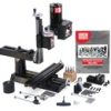
14″ 8-direction Mill
The Deluxe 8-Direction Milling Machine is one of the most versatile mills Sherline offers. In addition to standard X-, Y-, and Z-axis movement, this model provides five additional directions of headstock adjustment—allowing you to position the spindle for drilling or milling operations from nearly any angle.
- The headstock pivots up to 90° left or right.
- The column bed also rotates side to side up to 90°, enabling angled drilling.
- A specialized knuckle joint allows the column to tilt front to back.
- The ram-style column base can swing side to side up to 90°, offering even greater flexibility.
- Loosening the column cap lets the ram move in and out, providing over 5.5″ of additional travel.
With this wide range of movement, the machining possibilities are nearly limitless within the compact work envelope of the machine. The 14″ base also increases Y-axis travel by 2″ compared to the Model 5400 mill, making it a powerful tool for advanced miniature machining applications.
The 8-direction benchtop mill is ideal for users who need a small, precision milling machine capable of high-accuracy work. Like all Sherline mills, it is made in the USA and supported by unmatched customer service. Despite its compact size, this 14″ benchtop mill is engineered to handle wood, plastic, aluminum, and even steel—delivering full-size machine precision in a desktop footprint.
Note on Ordering a Metric Mill – Most Sherline cutting tool, such as center drills, are offered in fractional sizes. If you opt for a metric machine with metric collets or holders, you’ll need to order compatible fractional-size holders to use these tools effectively.
Standard Equipment for the 8-Direction Benchtop Mill
- A powerful 90V DC motor with electronic speed controller
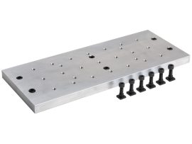
- 14″ base with laser-engraved scales
- Brass leadscrew cover that keeps chips off the rear of the Y-axis leadscrew
- 2.75″ (70 mm) x 13.0″ (330 mm) table with laser-engraved scales and two T-slots
- 2″ column riser block
- Resettable, zero-adjustable handwheels:
- (2) 2″ (51 mm) handwheels on X- and Y-axes
- (1) 2-1/2″ (63 mm) handwheel on Z-axis
- All with laser-engraved aluminum collars
- ¼” Drill Chuck w/ key, #1 Morse arbor with drawbolt
- Pulleys, drive belt, three hexagonal keys, spindle bars, gib removal tool, eight-foot three-wire power cord, and instruction manual
- Oil reservoirs on the X/Y axes and the Z axis help keep critical parts lubricated. These were initially developed for CNC machines that run constantly for hours on end but can benefit manual machines as well
-


Related products
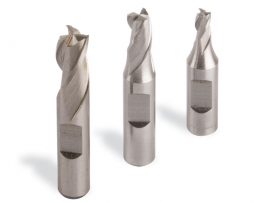
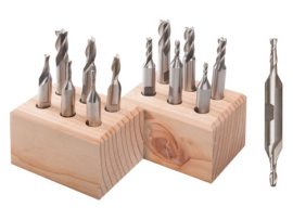
1/4″ 3-Flute End Mill Set
1/4" Shank 3-piece, 3-flute End Mill Set (1/8", 3/16", 1/4")